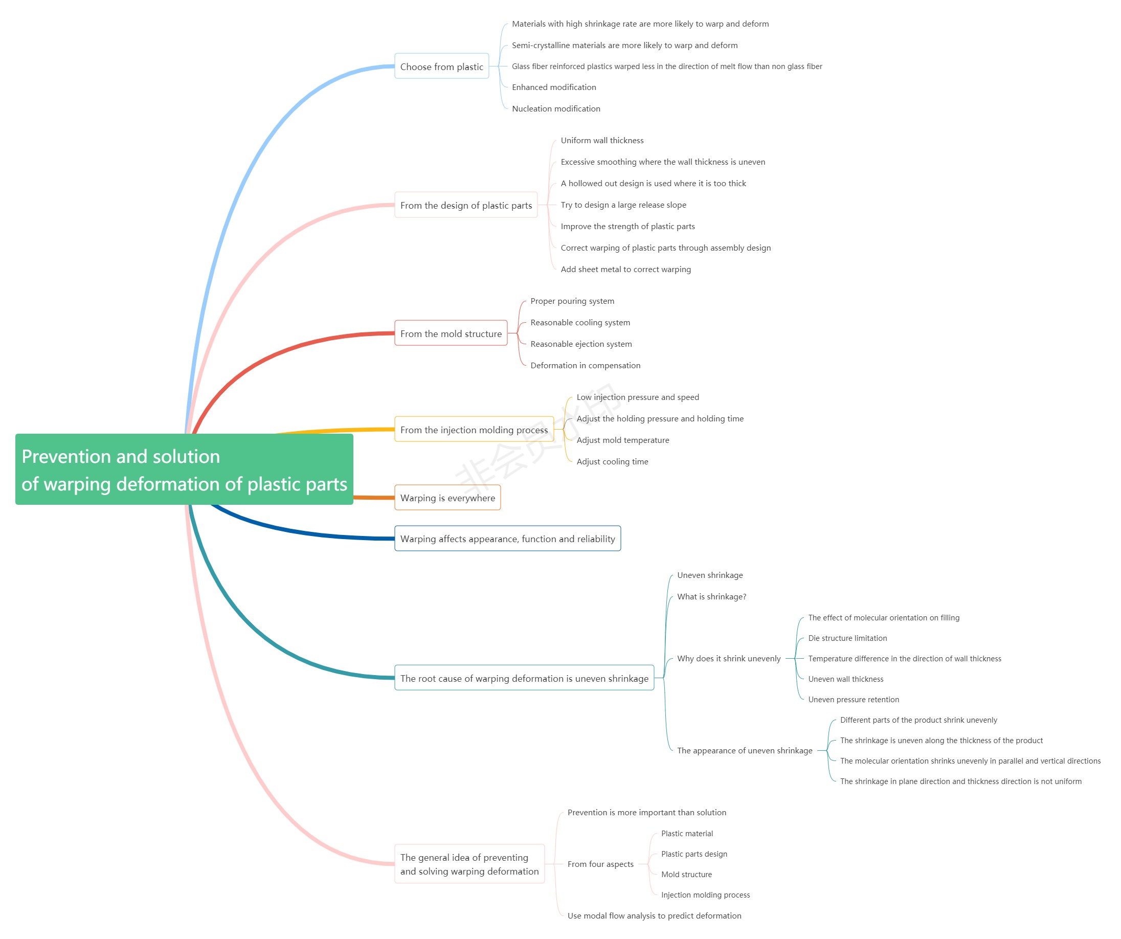
Plastic parts warping deformation, is one of the most likely defects in plastic parts, in any product may occur; At the same time, it is one of the most difficult defects to solve.

Here are the various warping deformations:
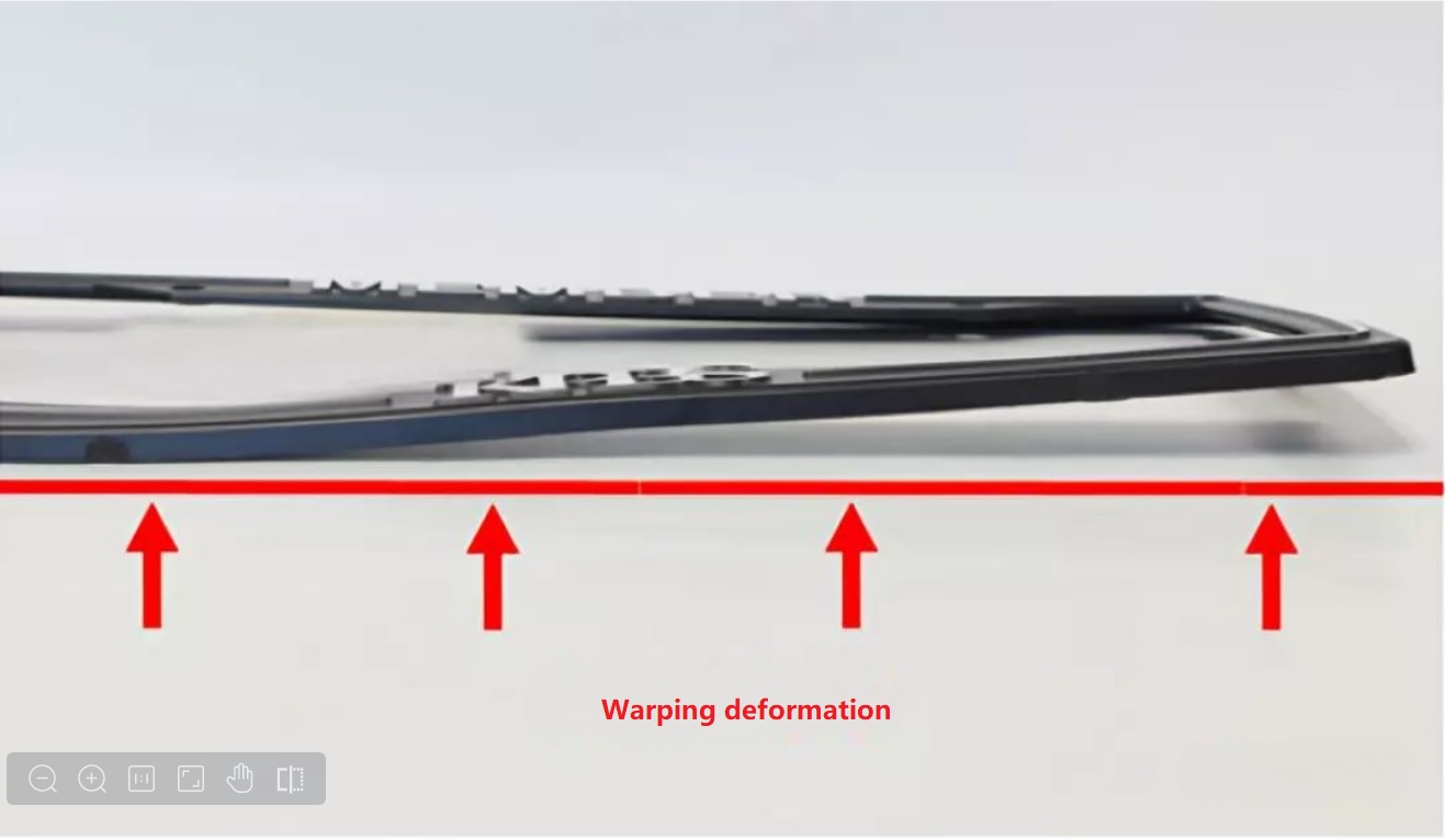
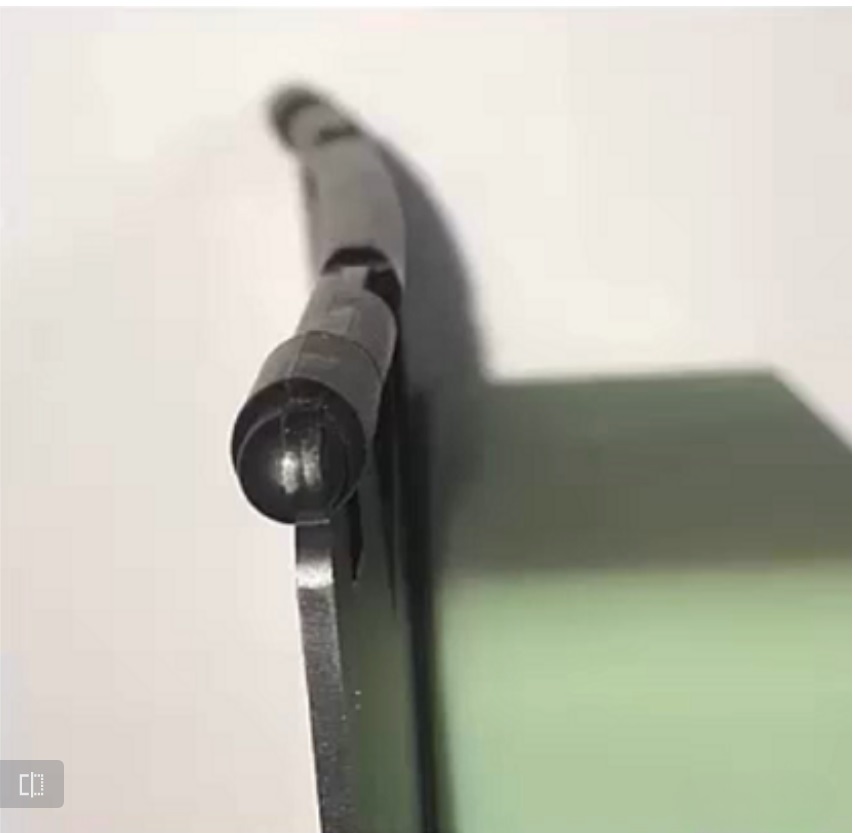
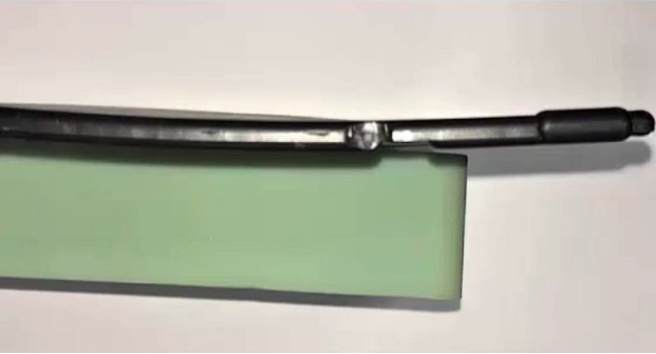
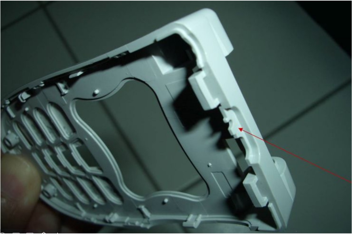
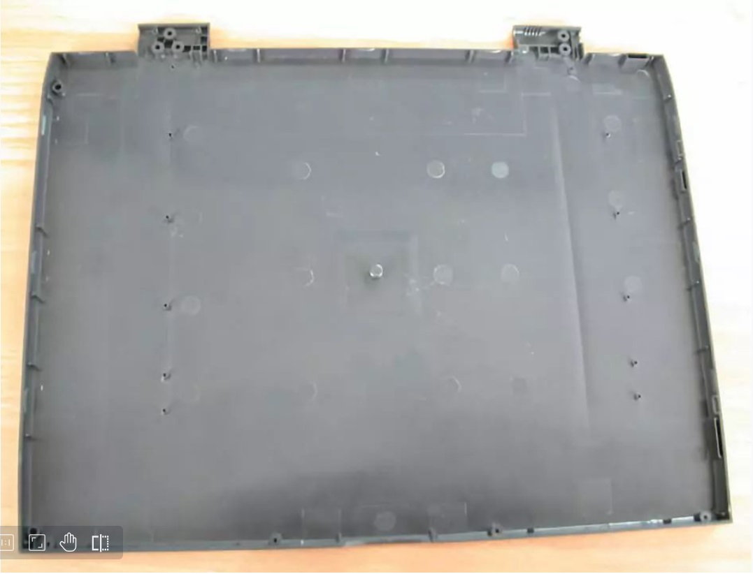
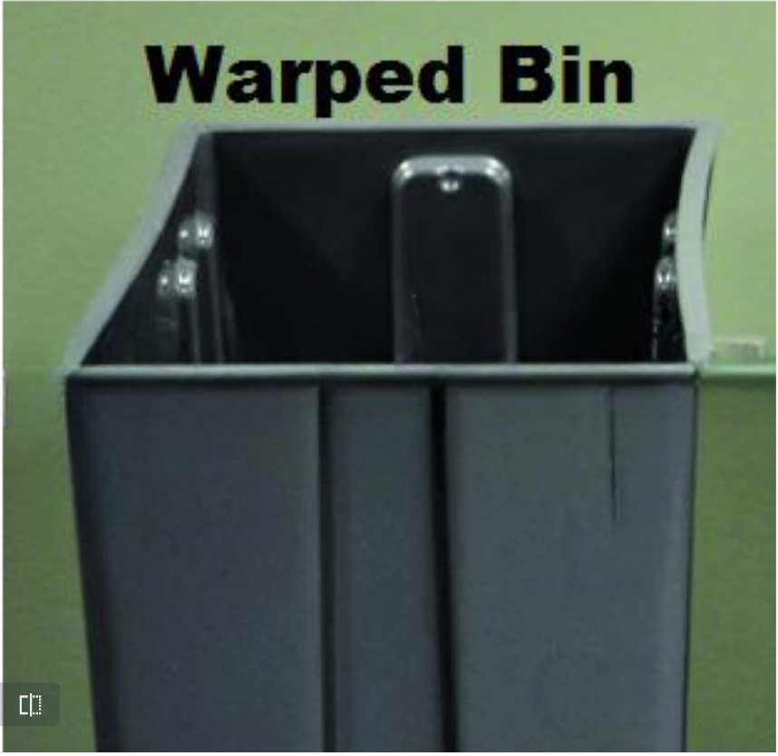
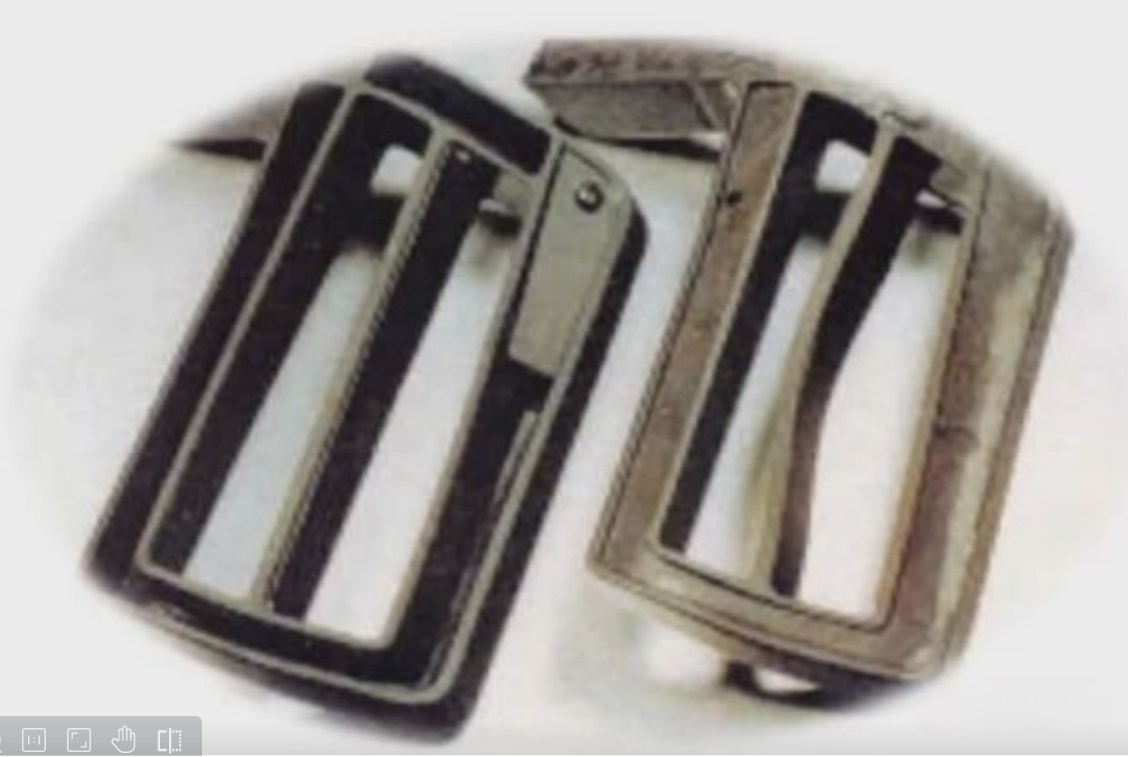
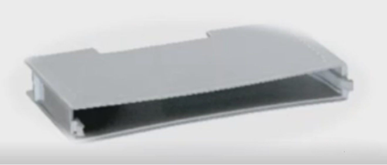
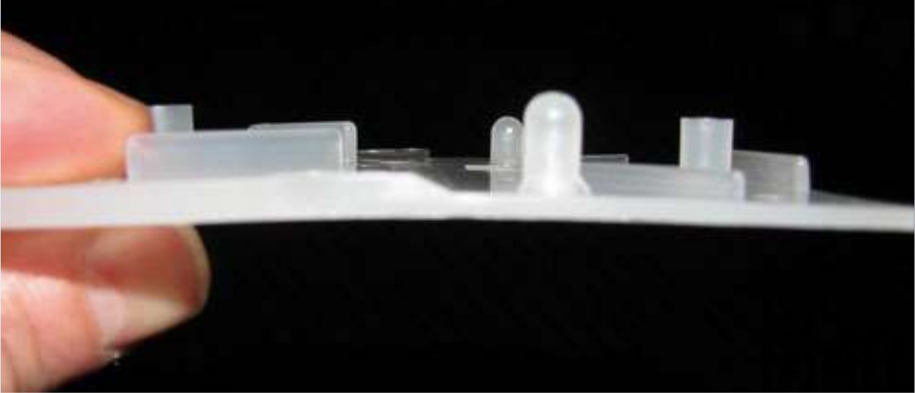
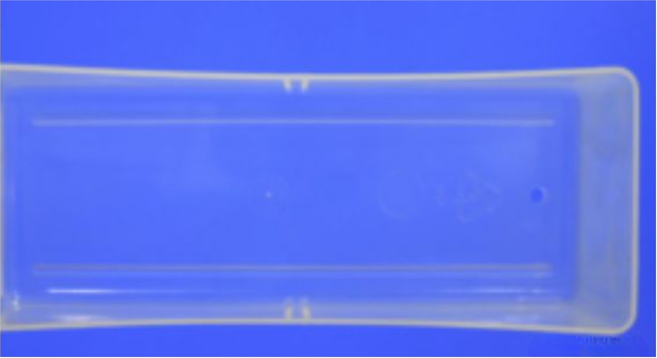
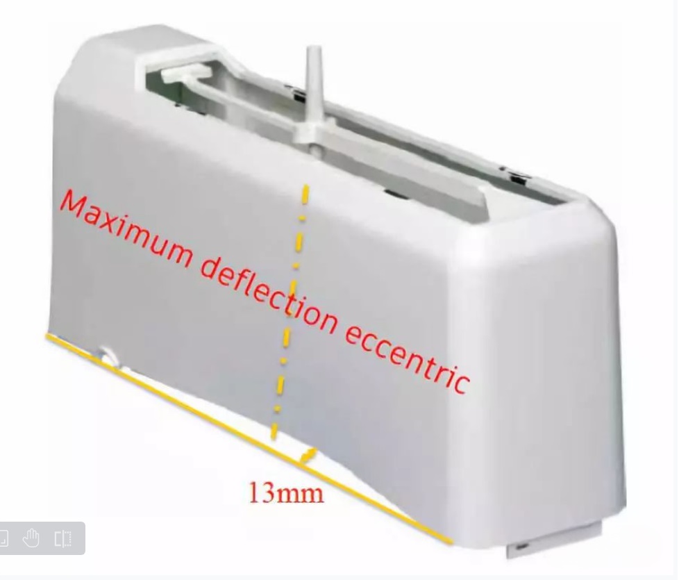
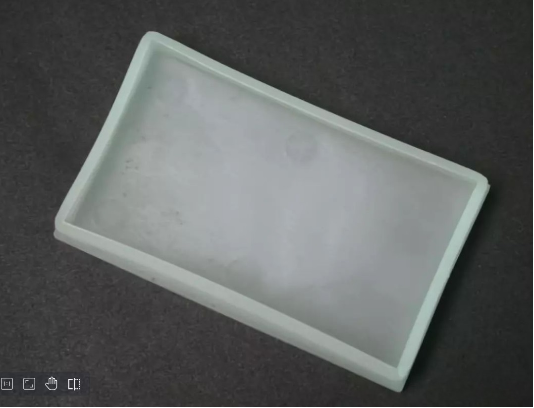
General warping deformation will cause inconsistent appearance gap, there is a break difference, affect the appearance of the product, consumers may feel that the product grade is too low and give up buying.
Serious warping deformation will affect the assembly of products, and even affect the function, performance and reliability of products.
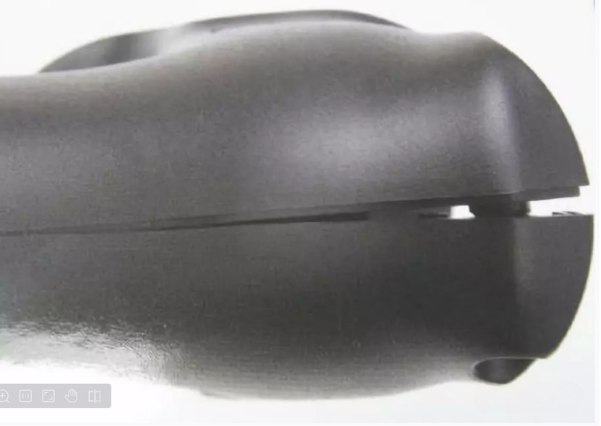
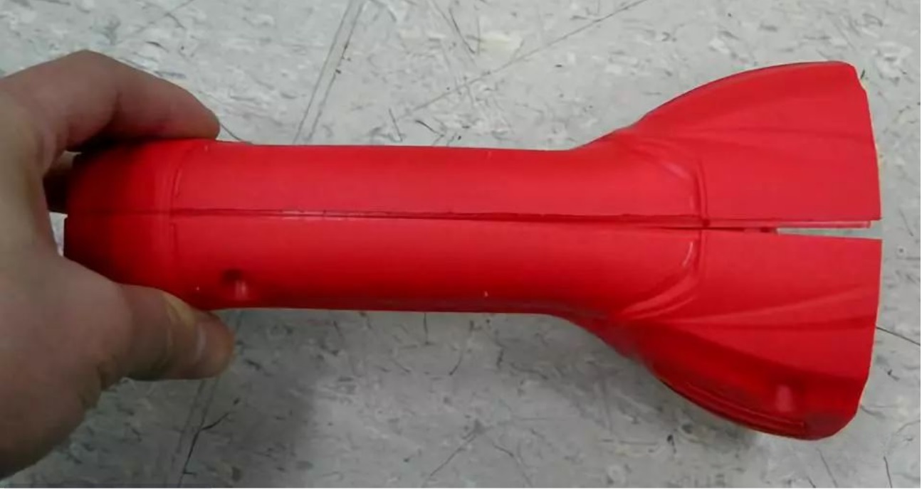
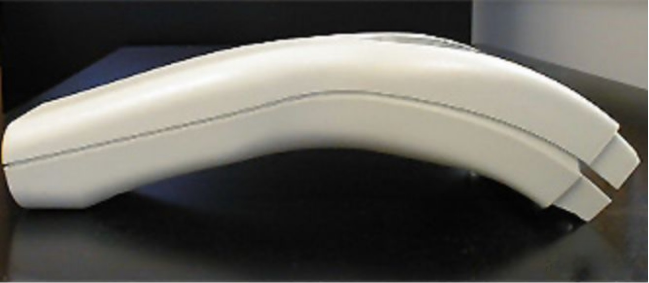
▲ Warping caused the appearance of the gap is inconsistent, seriously affecting the product beauty
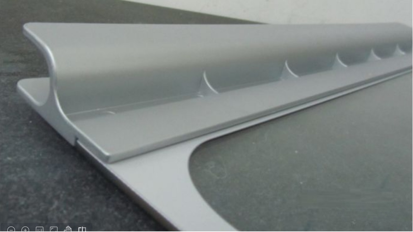
▲ Warping caused by washing machine gripper and glass cover plate bonding is not firm
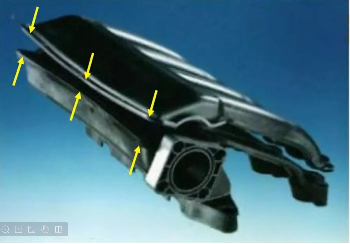
▲ Warping affects assembly quality, reduces product strength and performance, and has potential failure risk
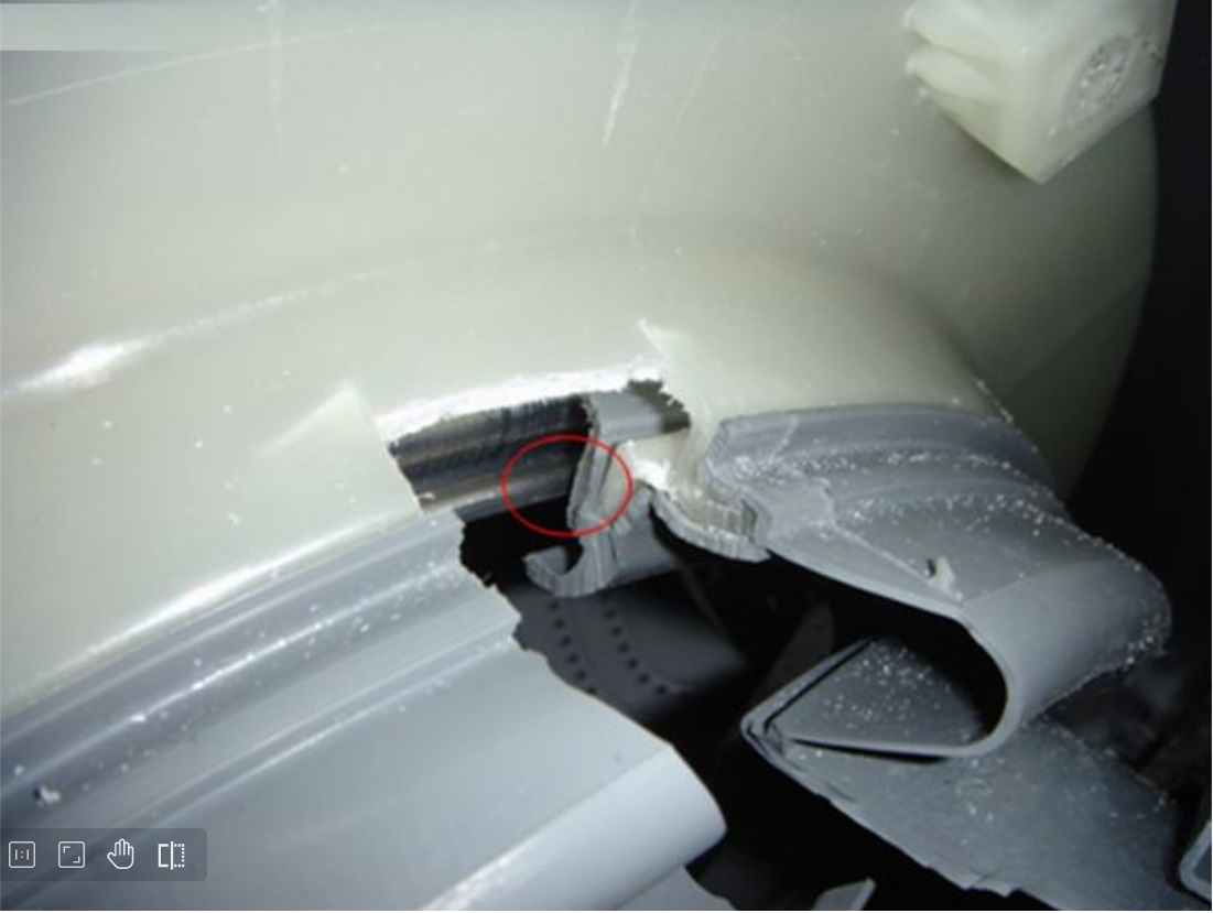
▲ Drum washing machine front bucket product head warping deformation resulting in sealing ring and stainless steel inner bucket clearance is too small, sealing ring and stainless steel inner bucket wear, seriously affecting product reliability
3.1 Why is uneven shrinkage the root cause of warping deformation?
The fundamental cause of plastic parts warping deformation is the uneven shrinkage of plastic.
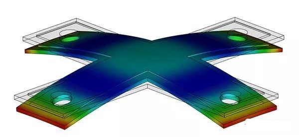
▲CAE software simulation contraction is not uniform
If the plastic parts shrink evenly in all directions during the injection molding process, the size of the plastic parts will shrink at the same time, but will maintain the correct shape, without warping deformation.
However, if the contraction in either direction is inconsistent with the other, this will result in internal stress, and when the internal stress exceeds the strength of the plastic, the plastic will warp and deform after ejection.
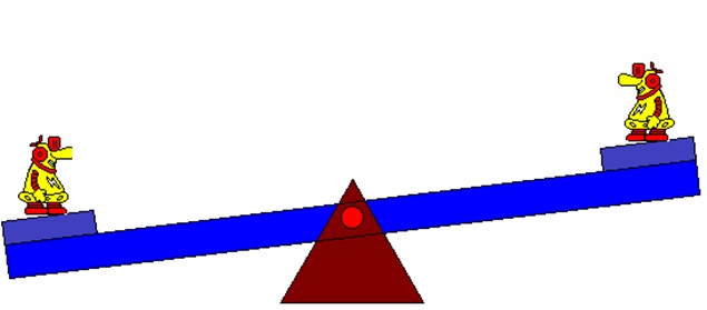
▲ The left side of the internal stress caused by uneven contraction is the right side of the strength
3.2 What is shrinkage?
Before we can understand the non-uniform shrinkage, we need to understand the shrinkage of plastic materials.
Therefore, it is necessary to start from the molecular structure of plastic materials, and look at the various changes in the melting and cooling process of plastic materials.
For most plastic materials, the properties of the melting and cooling process depend on the type of plastic and whether fillers or glass fibers are added.
1) Amorphous plastic refers to a plastic in which the molecules are arranged with each other without a crystal structure.
Common amorphous plastics include ABS, PC, PMMA and PPO. The molecular arrangement of amorphous plastics is disordered in both molten state and solid state.

When amorphous plastic melts, the forces between the molecules weaken, allowing them to move against each other. In addition, shear forces (similar to friction) during the filling phase cause the molecules to unfold and Orient in the same direction as the flow.

When the flow stops, the molecules relax and return to their original disorder. The forces between the molecules bring the molecules closer together until the temperature is low enough for them to solidify.
These forces cause uniform contraction, but the relaxation effect causes more contraction in the flow direction.
2) Semi-crystalline plastics
Semi-crystalline plastics refer to the plastics in solid state where some molecules are arranged with each other in a regular crystal structure, and the crystal structure of this part is relatively dense and tighter. Common semi-crystalline plastics include PBT, PA, POM, PPS, PEEK, etc.

When the semi-crystalline plastic melts, the crystalline part loosens and the molecular orientation is consistent with the flow direction of the molten current, which is roughly the same as that of the amorphous plastic. But when it cools, it doesn't relax.
Instead, they remain in the same direction as the flow and begin to crystallize, significantly increasing the shrinkage rate. The relaxation effect makes the shrinkage rate of the flow direction much larger than that of the vertical direction.
The shrinkage rate of semi-crystalline plastics is higher, and the shrinkage rate of semi-crystalline plastics is different in parallel and perpendicular to the flow direction of the solution, which makes the problem more complicated. This problem is further complicated by the change of crystallinity due to the change of injection molding process conditions. If the plastic cools slowly, crystallinity and shrinkage increase.
3) Glass fiber reinforced plastics
Glass fibers are often added to plastics for mechanical strength or other properties. When glass fibers are added to plastic, they may counteract the contraction caused by molecular orientation described above.
The glass fiber does not expand or shrink when the temperature changes. Therefore, the glass fiber will significantly reduce the shrinkage rate of the plastic in the direction of the solution-flow.

▲ no filling PP shrinkage rate

▲ Glass fiber filled PP shrinkage rate
3.3 Why does it shrink unevenly
What causes the uneven contraction? There are five main reasons for this.
1. Influence of molecular orientation during filling
At the beginning of filling, shear pressure causes the plastic molecules to align. When the filling stops, the plastic solution remains at a high temperature, the shear force disappears, and the orientation relaxes (the orientation is maintained only when shearing and curing occur simultaneously).
For amorphous plastics, when the orientation is relaxed, the shrinkage parallel to the flow direction of the solution is greater.
For glass fiber reinforced plastics, the shrinkage is larger perpendicular to the flow direction of the solution, because the molecular orientation of the crystalline part is consistent with the flow direction of the solution, and crystallization will occur perpendicular to the flow direction of the solution.
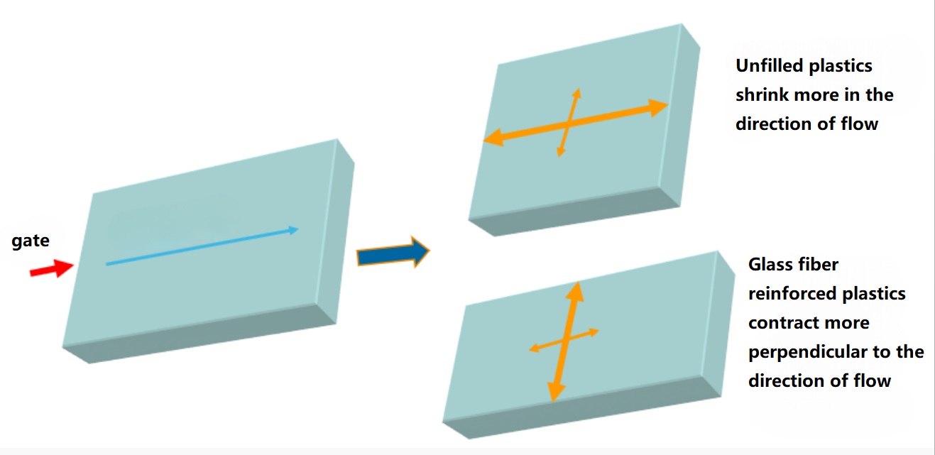
▲ Molecular orientation of non-filled plastics and reinforced plastics
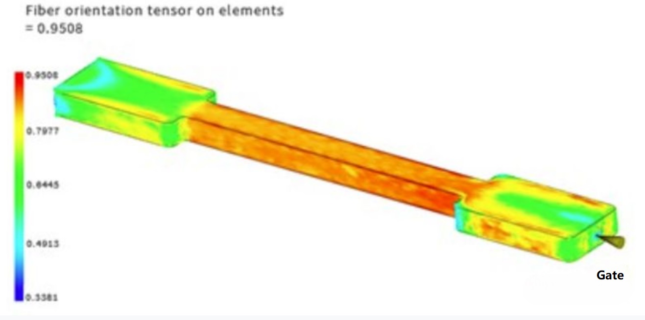
Red: consistent with the flow direction of the solution
Blue: perpendicular to the solution flow direction
2. Mold structure limitation
When the plastic part is in the mold, due to the limitations of the mold structure, the plastic part cannot shrink in the plane direction, but it can shrink in the thickness direction.
This has two effects: first, greater shrinkage in the direction of thickness; Secondly, the residual internal stress concentrates in the plane direction.
After ejection, due to the absence of mold structure, as the plastic parts continue to cool, the stress release causes warping deformation.
The higher the mold temperature, the slower the cooling rate, the more stress release.
The influence of mold structure limitation is influenced by plastic material. Plastic materials with slower stress release have greater linear shrinkage; Plastic materials with faster stress release have less linear shrinkage;
3. Temperature difference in the direction of wall thickness
When the mold temperature on both sides of the thickness direction of the plastic parts is inconsistent, the contraction on both sides is uneven.
Generally speaking, the high die temperature side shrinks more, and the low die side shrinks less, resulting in a bending moment leading to the warping deformation of plastic parts.
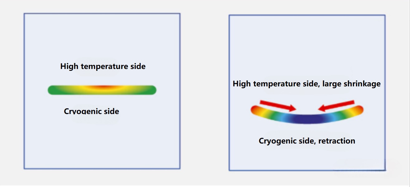
▲ Influence of die temperature difference on shrinkage
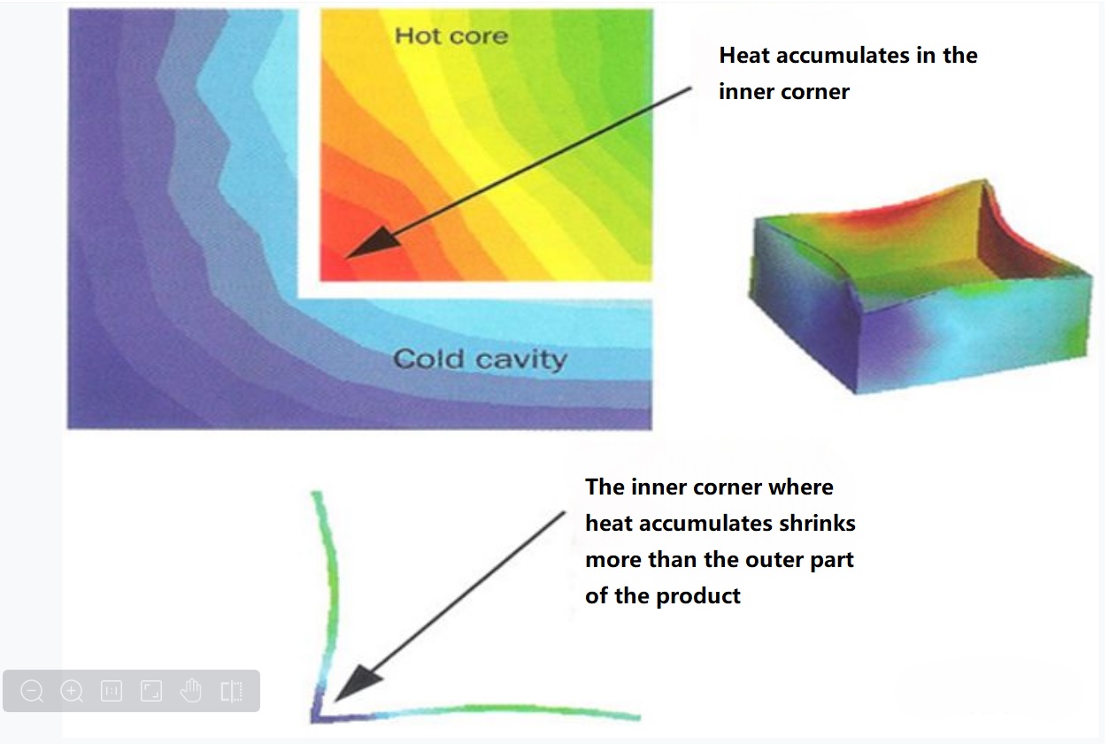
▲ The temperature difference at the corner of the box plastic parts
4. Uneven wall thickness
When the plastic parts have uneven wall thickness, the thick area needs longer cooling time, resulting in greater shrinkage.
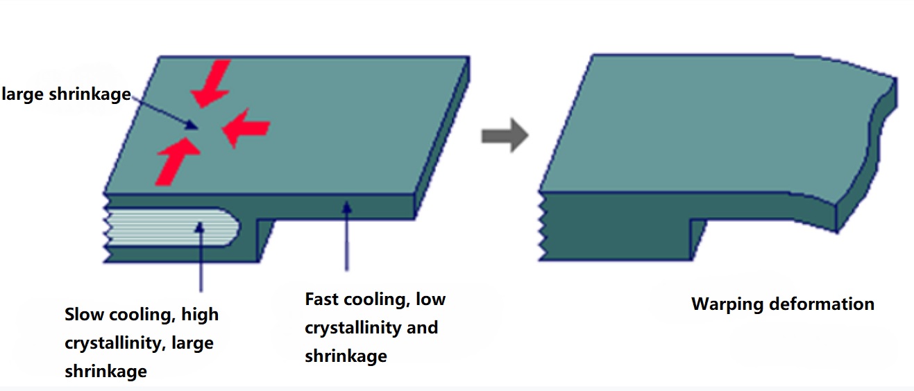
▲ The thickness of the wall and the thickness of the wall shrink differently
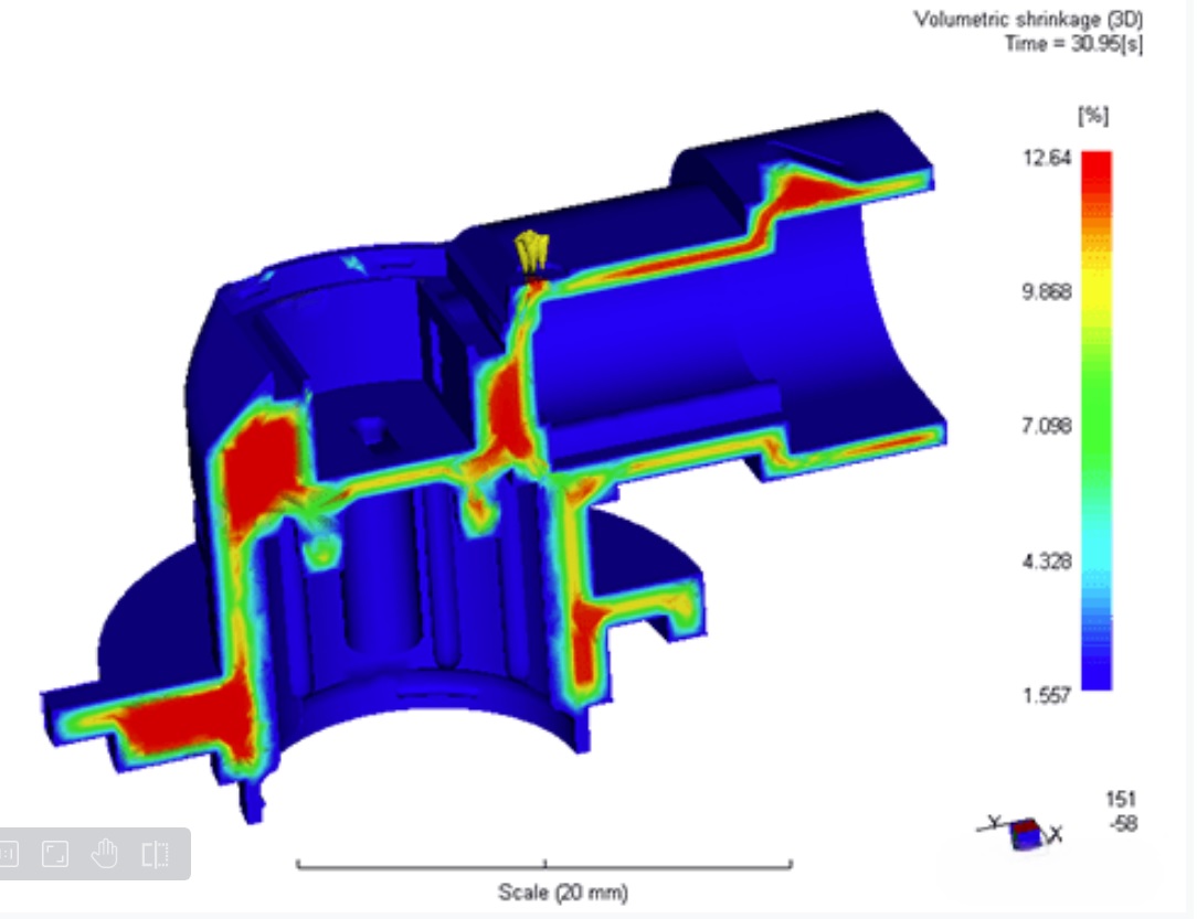
▲ Different wall thickness shrinkage is different - red represents high shrinkage rate
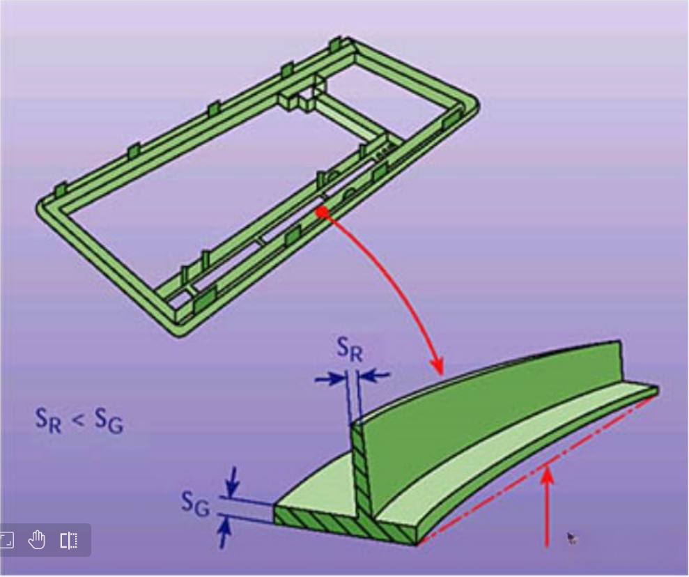
▲ Warping deformation occurs when the wall thickness is uneven
5. Uneven pressure retention
The internal pressure of the plastic parts is uneven.
The pressure of the gate attachment area is large, and the pressure of the area far away from the gate will cool at different speeds, resulting in uneven shrinkage.
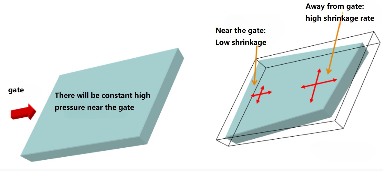
3.4 Four manifestations of uneven contraction
Generally speaking, the uneven shrinkage is mainly manifested in four aspects:
1. Uneven shrinkage of different parts of the product
The area near the sprue and the final filling area on the plastic parts shrink unevenly. The area near the gate shrinks and the final filling area shrinks.

▲ The middle contraction is greater than the periphery, resulting in saddle-shaped warping

▲ The contraction around is greater than the middle, the middle concave or convex
2. Uneven shrinkage along product thickness direction
If you look at the thickness profile of a plastic piece, the upper and lower regions of the profile shrink unevenly. This inconsistency will cause the plastic to warpage because one side shrinks more and the other shrinks.
3. Uneven shrinkage of molecular orientation in parallel and vertical directions
Due to molecular orientation or fiber orientation, the shrinkage is uneven in the direction parallel to and perpendicular to the flow direction of the plastic part solubilization.
As mentioned above, unfilled plastics contract more in the direction of solution-flow, while glass fiber reinforced plastics shrinkage more in the vertical direction.
4. Uneven shrinkage in plane direction and thickness direction
Plastic parts usually shrink more in the thickness direction than in the plane direction, mainly because there is a mold structure restriction in the plane direction, but not in the thickness direction.
This uneven shrinkage can lead to warping deformation, especially at the corners of plastic parts, where the wall thickness of the part is usually greater than the basic wall thickness of the part.
4.1 Prevention is more important than solution
The warping deformation of plastic parts must be prevented in advance in the product design stage of plastic parts. It is too late to solve the problem when the mold processing is completed and the problem of warping deformation is found in the mold test.
Once the warping deformation of plastic parts occurs, it is very troublesome to solve, and the means that can be used are often few and helpless:
4.2 Structured ideas for preventing and solving warping deformation
To prevent and solve the warping deformation problem, we need to start from four aspects: material selection, plastic parts design, mold structure and injection molding process.
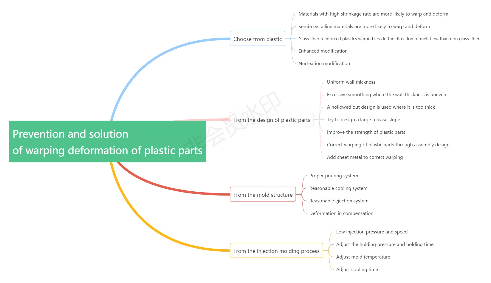
4.3 Prevent warping deformation by using mold flow analysis software
It is a very mature and effective method to use the mold flow analysis software to accurately predict the trend of product warping deformation before the mold is opened, and carry out targeted optimization design to reduce the warping deformation.
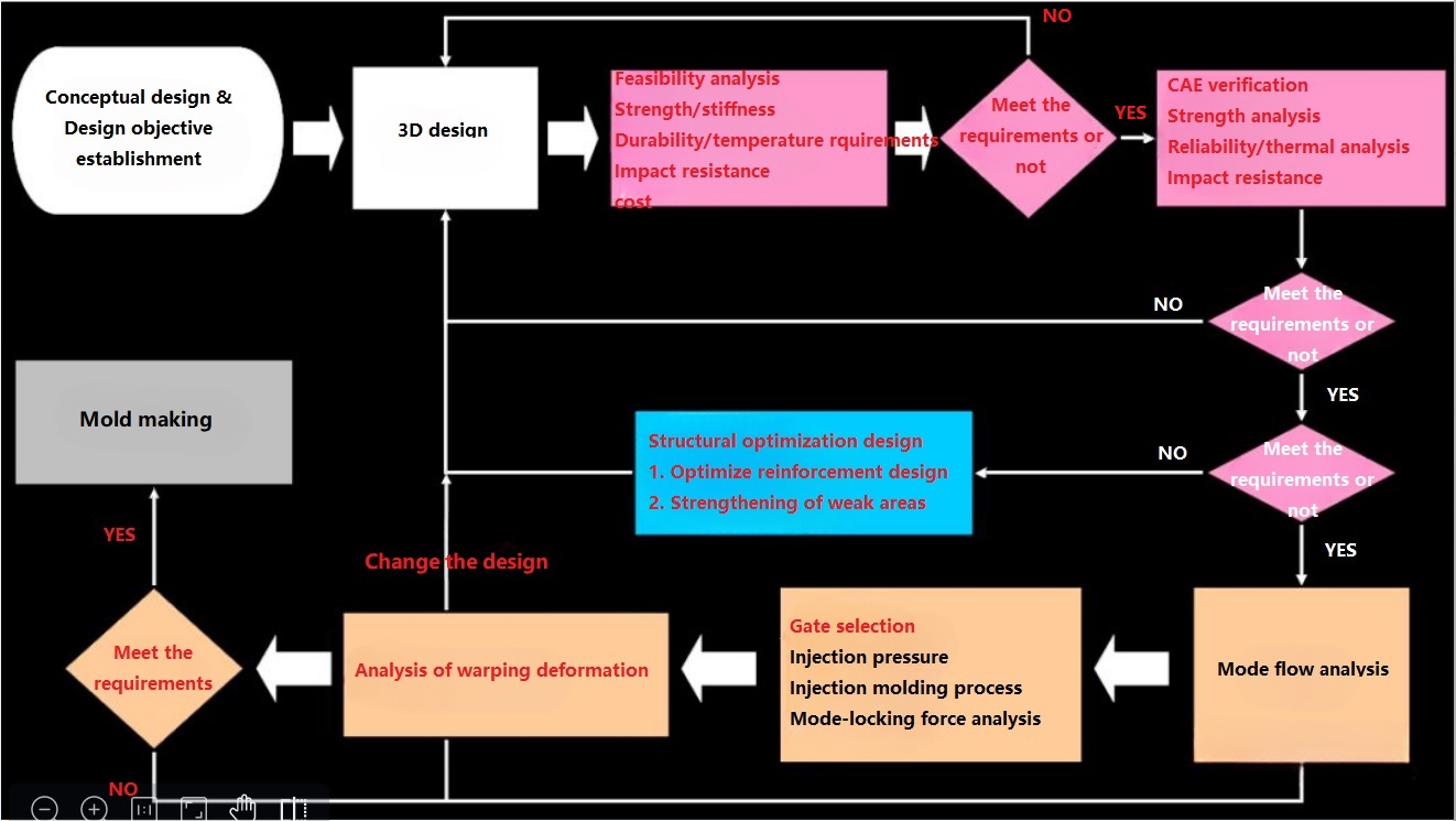
▲ The use of mold flow analysis software to prevent warping deformation process
The shrinkage rate, fluidity, glass fiber content and temperature resistance of plastic materials have an impact on the buckling deformation of the product. Under the same other conditions, the buckling deformation of different plastic materials is different.
Compared with amorphous plastics, semi-crystalline plastics are more likely to warp and deform.
Compared with non-glass fiber reinforced plastics, the warpage deformation in the flow direction of the solution is smaller.
According to the requirements of the application scenarios of plastic parts, plastic materials with low warpage possibility should be selected for situations requiring high dimensional accuracy.
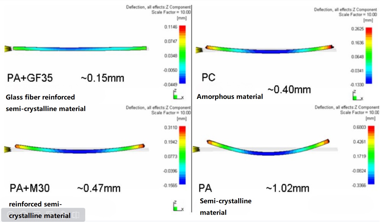
▲ There are differences in warping deformation of different materials
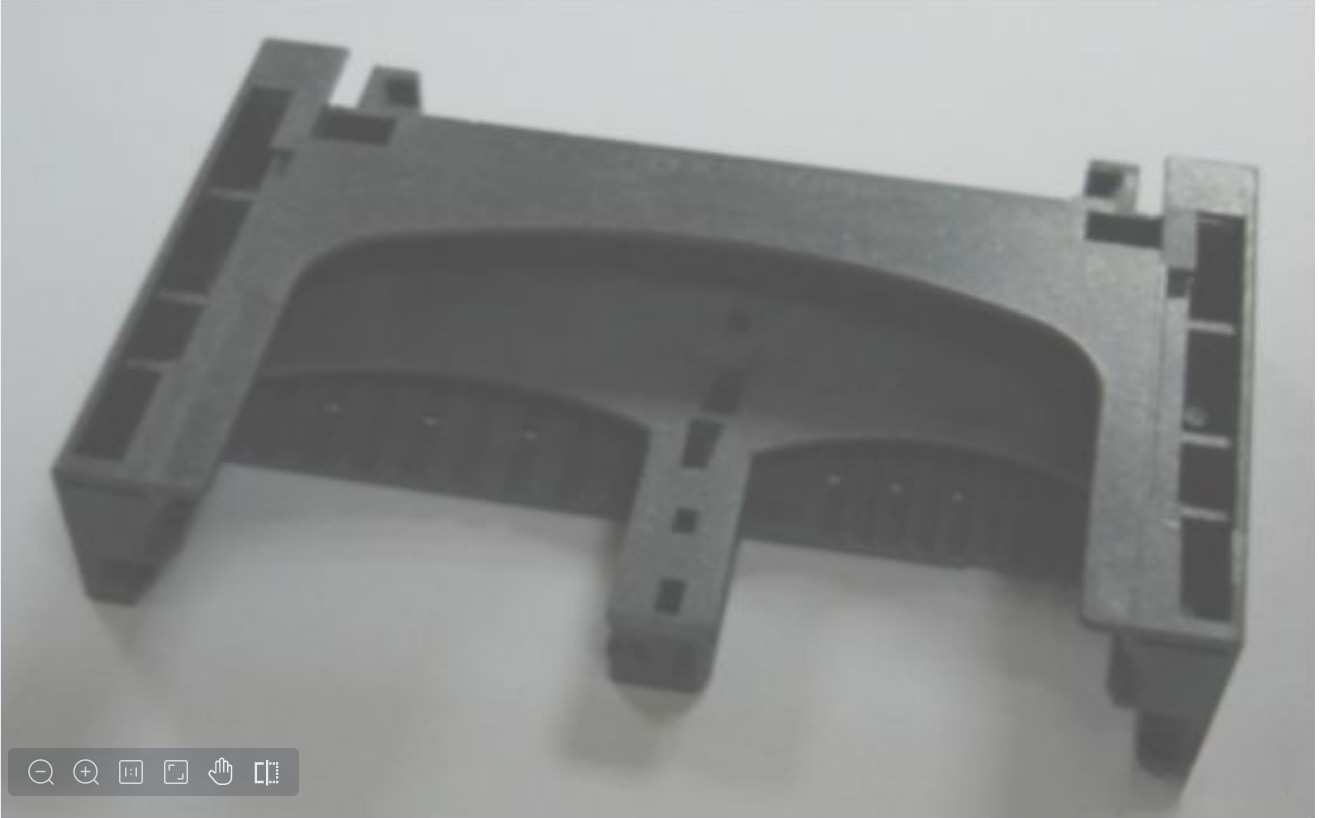
▲ Card reader 4 in 1 card material changed from PA9T to LCP, warp deformation reduced from 0.15mm to 0.05mm
6.1 Uniform wall thickness
Uneven wall thickness is one of the fundamental causes of plastic parts warping and deformation. Therefore, when designing plastic parts, it is necessary to follow the principle of uniform wall thickness advocated in the book "Product Design Guide for Manufacturing and Assembly".
Where possible, try to make the wall thickness of the plastic parts even.

▲ Even wall thickness
6.2 Smooth transition where the wall thickness is uneven
Smooth transitions are needed where the wall thickness is uneven.
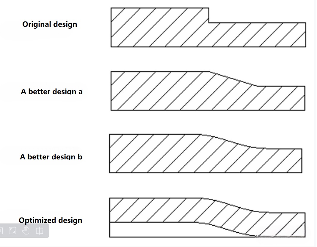
▲ Smooth transition at even wall thickness
6.3 Hollowed out design is used where the wall thickness is too thick
For any place on the plastic parts where the wall thickness is too thick, it is necessary to use a hollowed out design to make the wall thickness even.
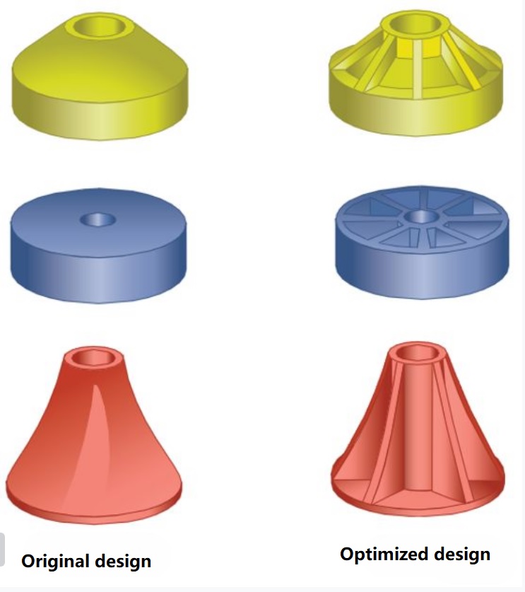
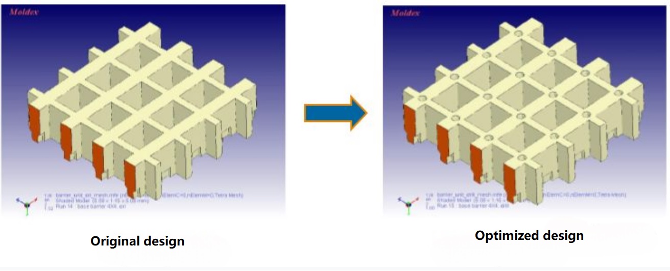
▲ The place where the wall is too thick is hollowed out
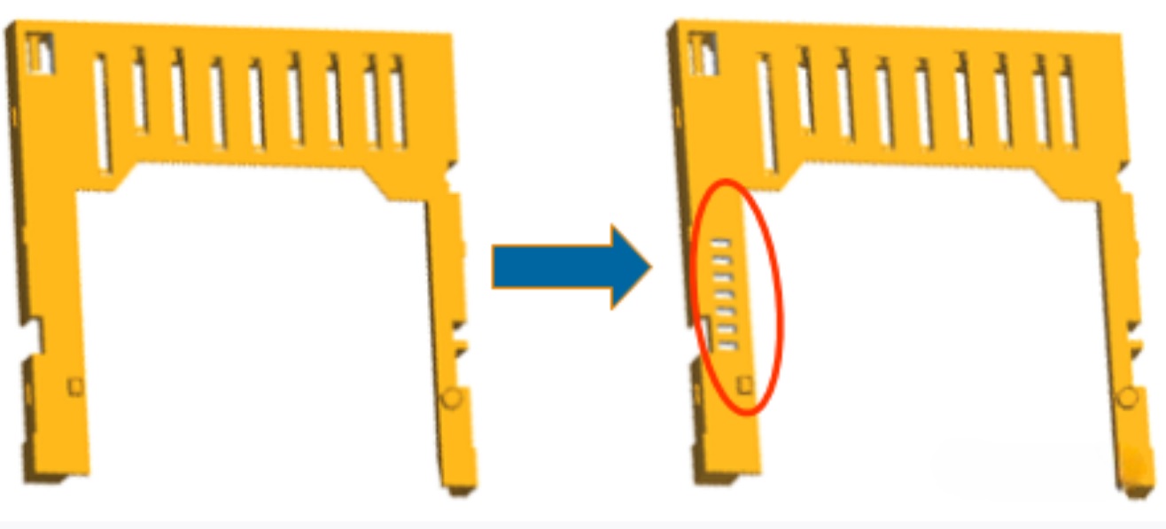
▲ Warpage reduced from 0.25mm to 0.06mm after using hollowed out design
6.4 Try to design a large demoulding slope
Try to design a large demoulding slope to avoid the buckling deformation due to sticking mold during ejection.
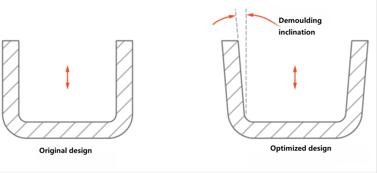
▲ demoulding slope
6.5 Improve the strength of plastic parts
For the lack of strength on the structure of plastic parts, the method of adding reinforcing bars should be used to improve the strength, to avoid deformation due to force when ejecting.
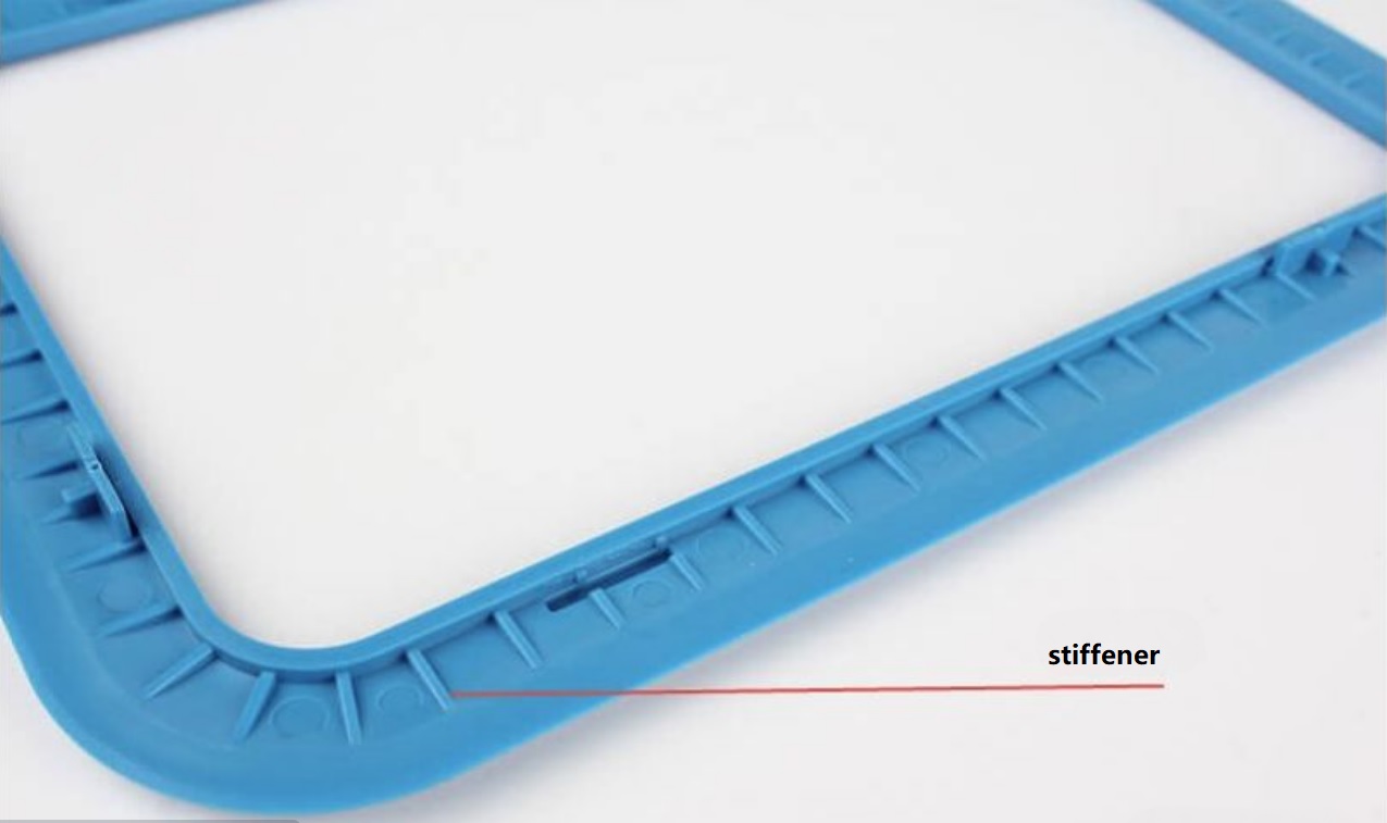
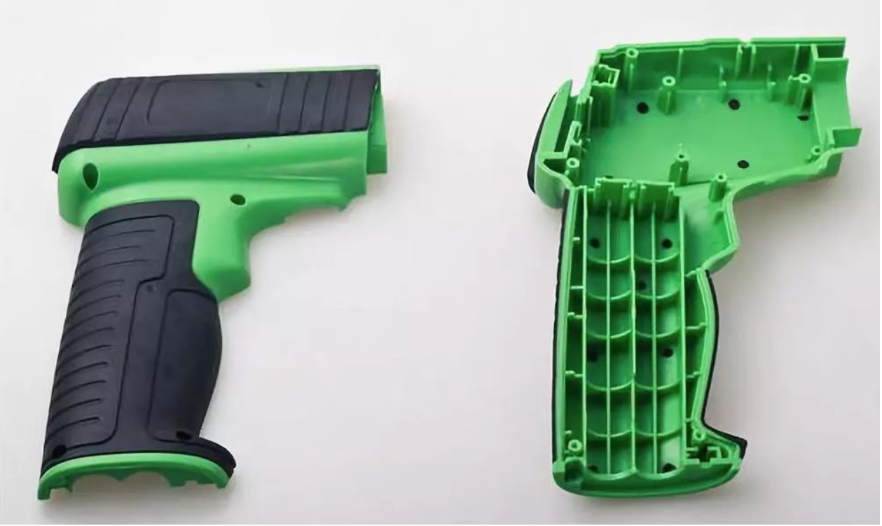
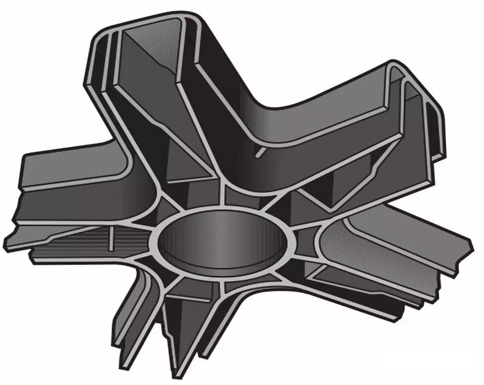
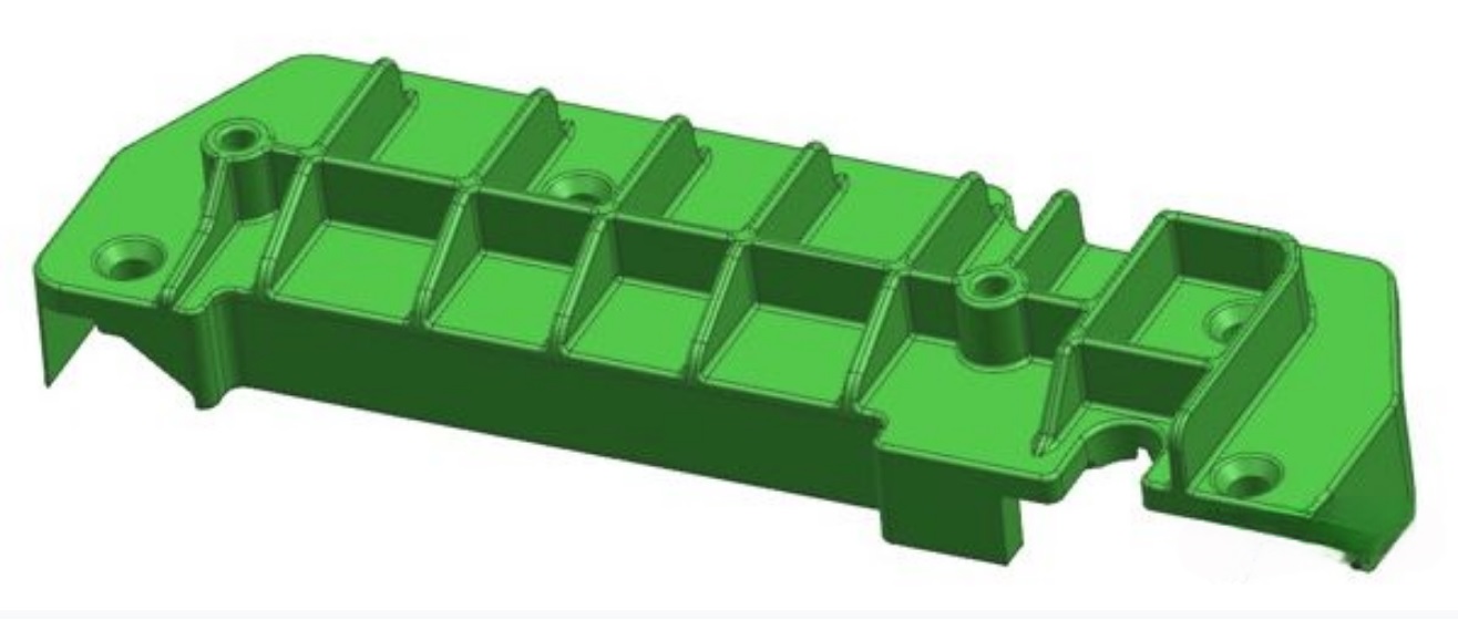
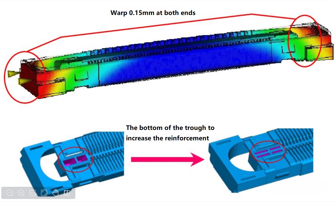
▲ Warpage decreased from 0.15mm to 0.05mm after adding stiffeners
6.6 Reasonable design of the structure of plastic parts
1. Change the L-shaped structure to T-shaped
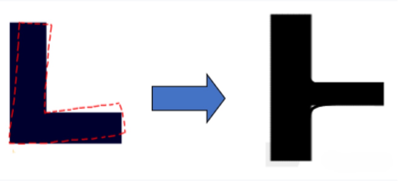
2. Change the T shape to a cross
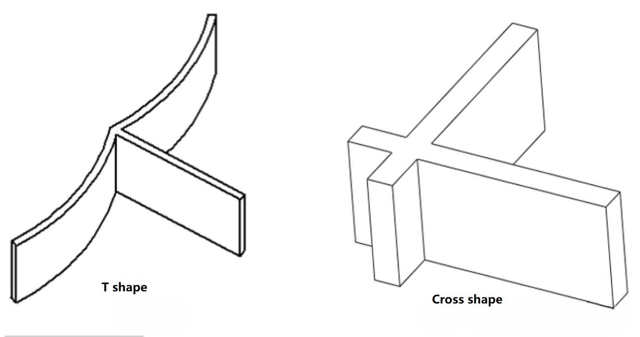
▲ Cross shape relative to T shape warping deformation is small
3. When the wall thickness is not uniform, the thickness can be kept unchanged and changed to symmetrical type.
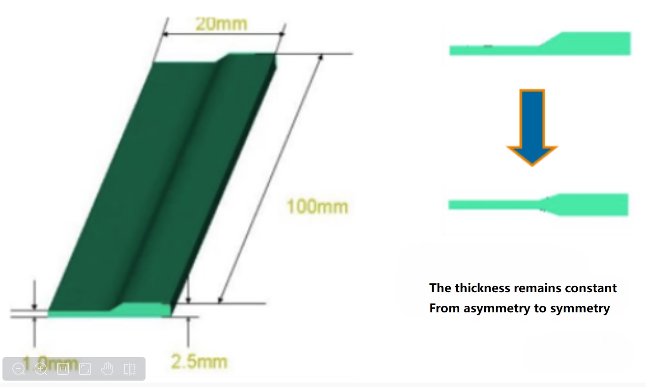
▲ Change asymmetry to symmetry
6.7 Correct the warping of plastic parts through assembly design
When the buckling deformation of plastic parts is inevitable, or the cost of various means to reduce the buckling deformation is too high, plastic parts can be placed in the product structure, through the design of other parts to correct the buckling of plastic parts.
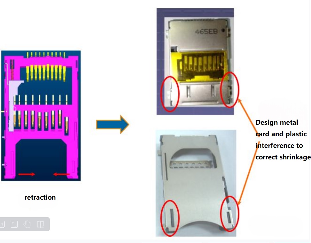
6.8 Add metal sheets to correct warping
Warping can be corrected by adding metal pieces to the plastic, but this method is expensive and is not recommended as a last resort.

The three major parts of the mold structure include pouring system, cooling system and ejection system, which have great influence on the buckling deformation of plastic parts.
7.1 Reasonable pouring system
The location, structure and quantity of injection mold gate affect the filling state of plastic in the mold cavity, which leads to the warping deformation of plastic parts.
1. The relationship between length ratio and warpage
When the molten material is filled, the molten material flows in the mold cavity. Generally, the temperature of the wall surface of the mold cavity is lower than the melting point of the plastic, so the molten material starts to cool from the moment it enters the mold cavity. A layer of melt in contact with the mold wall forms a non-moving shell (condensation layer), while the inside is still a relatively hot melt (flow layer).
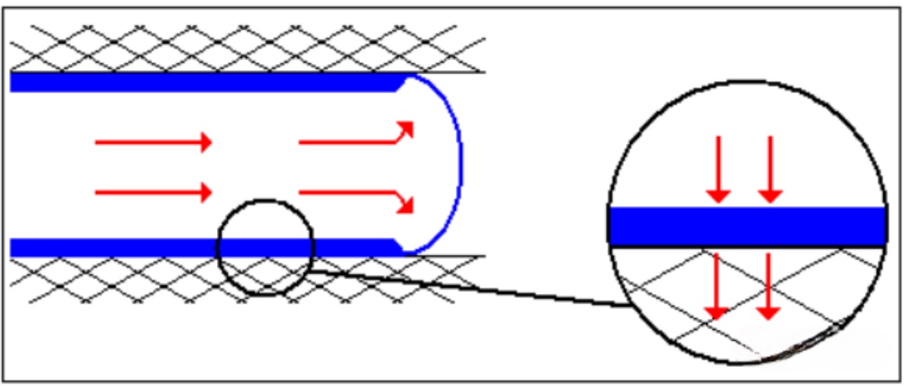
The longer the flow distance, the greater the internal stress caused by the flow and feeding between the frozen layer and the central flow layer. On the contrary, the shorter the flow distance is, the shorter the flow time from the gate to the flow end of the workpiece will be. During filling, the thickness of the frozen layer will be thinner, the internal stress will be reduced, and the warpage deformation will be greatly reduced.
The longer the melt flow distance in the mold cavity, the greater the probability of orientation stress. Therefore, for plastic parts with thick wall, long flow and large area, several gates should be distributed appropriately, which can effectively reduce orientation stress and prevent warping deformation. However, the gate is more likely to produce weld marks.
2. Relationship between flow balance and warping
Filling Pattern refers to the flow pattern of molten material changing with time in the conveying system and mold holes.
The filling mode has a decisive influence on the warpage of plastic parts. The ideal filling mode is that the melt reaches every corner of the cavity at the same time with the melt front velocity (MFV) during the whole filling process. Otherwise, the first filled area in the hole will overflow due to overfilling. However, if the mold holes are filled with changing melt front velocity, the molecular chain or fiber alignment will change.
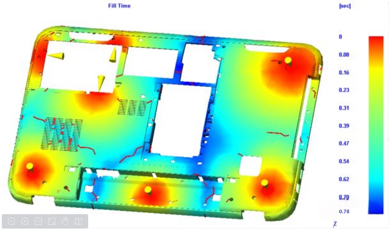
▲ This melt flow wavefront advance diagram can find that the product in large flow to balance, flow balance product pressure can be consistent to reach everywhere,
so as to effectively reduce the shrinkage and warping deformation of the product
3. Reasonable design of gating system
Reasonable design of pouring system is helpful to reduce the warping deformation of plastic parts.
1) The gate should be designed when the wall thickness of the plastic parts is maximum, which can properly reduce the injection pressure, pressure holding and pressure holding time, which is conducive to reducing the orientation stress. When the gate is designed at the thin-walled part, it is appropriate to increase the wall thickness at the gate to reduce the orientation stress near the gate.
2) The longer the melt flow distance in the mold cavity, the greater the probability of orientation stress. Therefore, for plastic parts with thick wall, long flow and large area, several gates should be distributed appropriately, which can effectively reduce orientation stress and prevent warping deformation.
3) The design of short and thick runner can reduce the melt pressure loss and temperature drop, and correspondingly reduce the injection pressure and cooling rate, so as to reduce the orientation stress and cooling pressure.
4) The design of the runner should be balanced to ensure the balanced feeding of each gate. Unreasonable channel design will lead to unbalanced material flow filling, and local locations may be overfilled, resulting in large extrusion shear stress, which is similar to the stress caused by excessive pressure preservation.
For example, the following figure shows the car audio panel. By optimizing the pouring system, the warpage deformation can be reduced;
Product size: 227.5×136.9×22.7mm
Basic wall thickness: 2.5mm
Forming material: PC+ABS Bayblend T65 Bayer
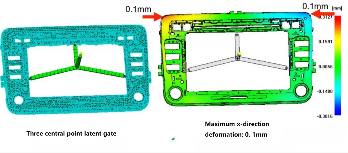
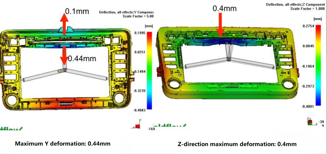
▲ Original pouring scheme, large warpage deformation
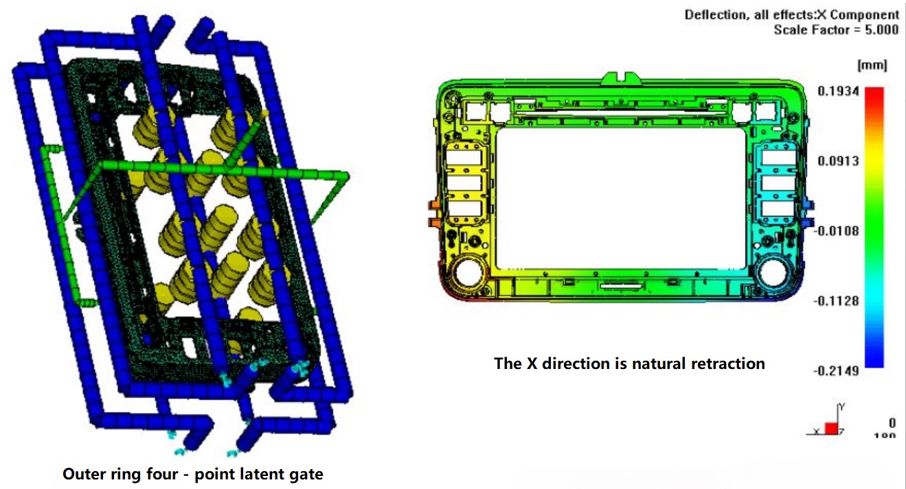
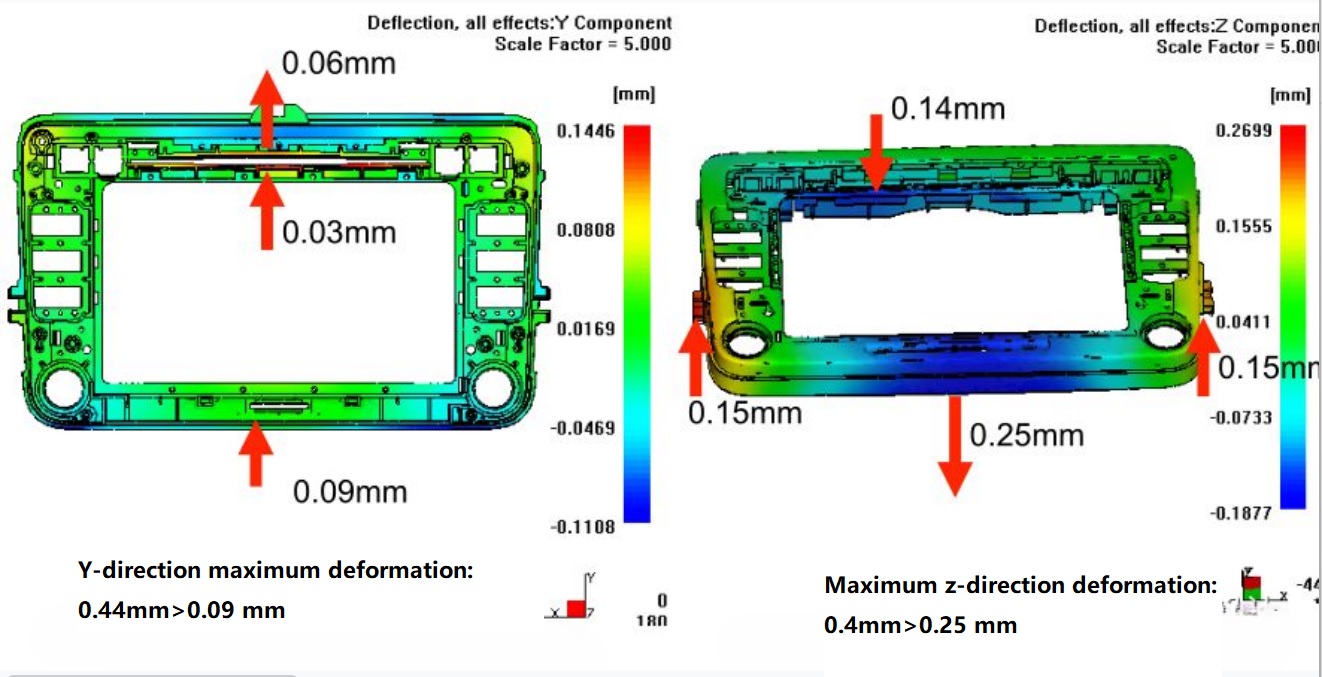
▲ Optimized pouring scheme, small warping deformation
7.2 Reasonable cooling system
Cooling water distribution should be uniform, so that near the gate, away from the gate area, wall thickness, wall thin place to get uniform and slow cooling, so as to reduce the internal stress.
1. Different mold temperature causes different warping deformation
When mold temperature on both sides of plastic parts is inconsistent, it will cause warping deformation.
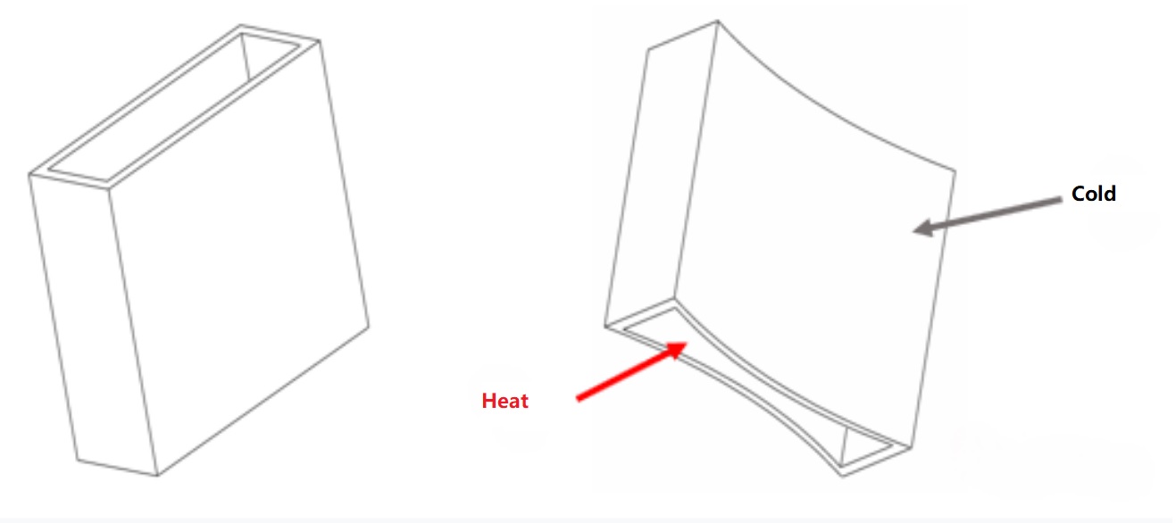
▲ When forming deep box plastic parts, if the internal cooling is not enough, after taking out the plastic parts, it will be deformed like the figure above.
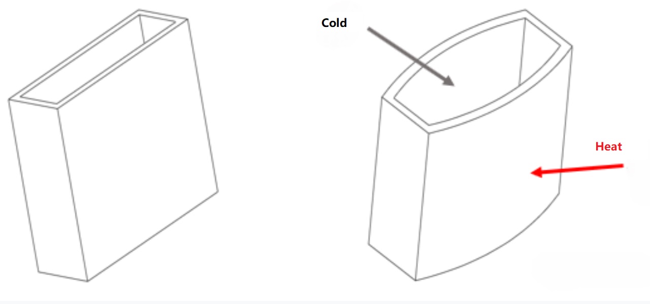
▲ When forming deep box shaped plastic parts, if the internal cooling is too much - for example, through the high-speed flow of cold water inside,
after taking out the plastic parts, it will be deformed as above.
2. Optimizing Cooling waterways -- Case 1
By optimizing the cooling channel, all parts of the plastic can be cooled simultaneously, thus reducing warping deformation.
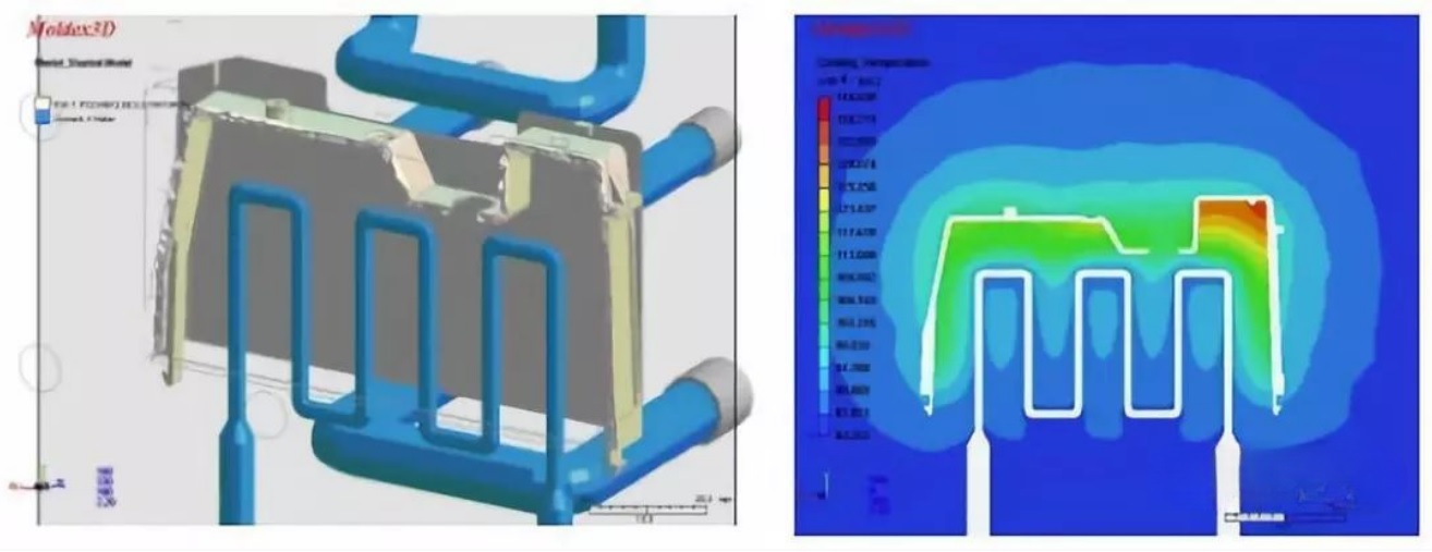
▲ The original cooling water design and mold temperature difference
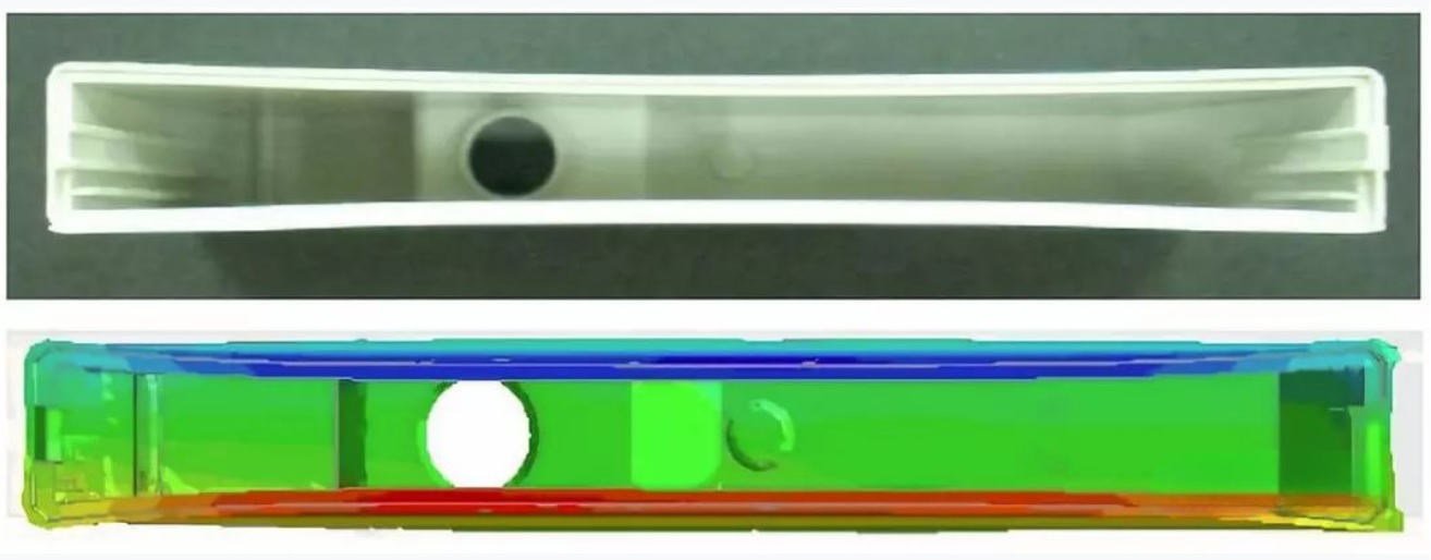
▲ The original cooling waterway design and processing of the physical and simulation
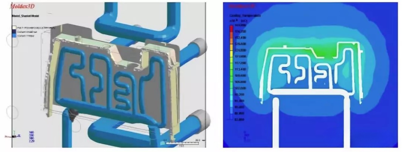
▲ Optimized cooling waterway design and mold temperature difference
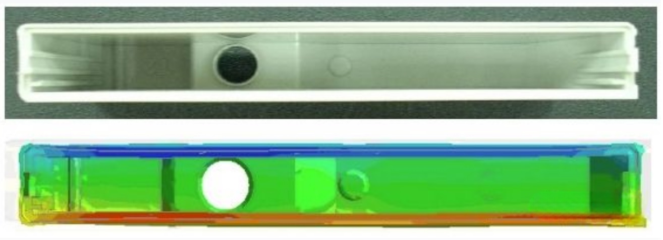
▲ Optimized cooling waterway design and processing of the physical and simulation
3. Optimizing Cooling waterways -- Case 2
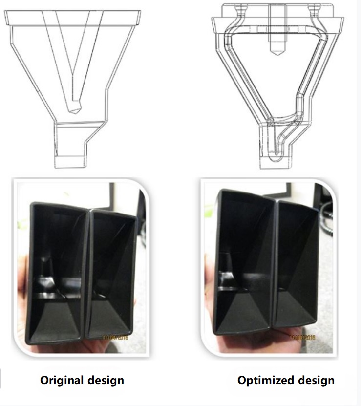
▲ Comparison of waterway design and processing
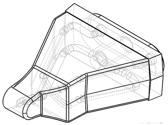
▲ Optimized waterway design
7.3 Reasonable Ejection System
The design of ejection system also directly affects the warping deformation of plastic parts. It is easy to warp and deform plastic parts due to unbalanced release force, uneven movement of push mechanism or improper ejection area.
To prevent ejection deformation, it is necessary to improve the demoulding conditions: such as balancing the output of the top, carefully polishing the new side, increasing the demoulding Angle, and arranging the ejector bar in the place where the demoulding resistance is larger, such as reinforcing bars and pillars.
7.4 Deformation pre-compensation
Deformation pre-compensation is to apply certain pre-deformation (reverse deformation) to the structure and size of the corresponding mold parts according to the deformation of the product predicted by the mold flow analysis software or the deformation of the plastic parts in the actual forming, so as to compensate the deformation in the forming, so as to achieve the purpose of reducing the warping deformation and improving the dimensional accuracy.
As shown in the picture, the plastic buckle is seriously deformed at the point indicated by the red arrow. However, conventional methods such as gate position adjustment and cooling system optimization cannot solve the deformation problem.
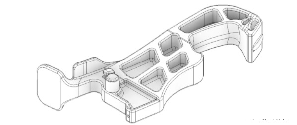
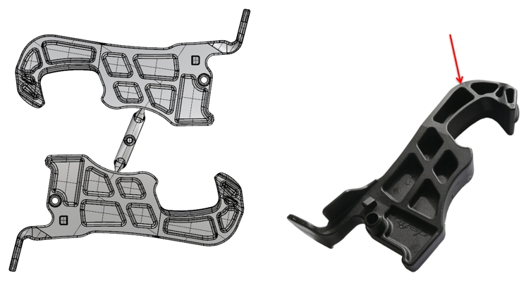
▲ Warping deformation is difficult to be solved by conventional means
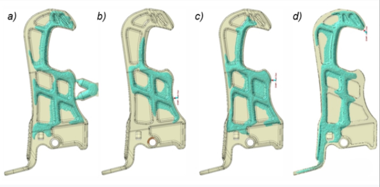
Through deformation precompensation, a certain predeformation is applied to the opposite side of the die; As shown in the figure, gray is the original mold structure, and blue is the predeformed structure in the opposite direction.
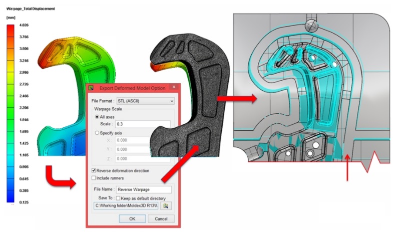
▲ Deformation pre-compensation
After deformation precompensation, the actual deformation of plastic parts is reduced from 1.86mm to 0.47mm.
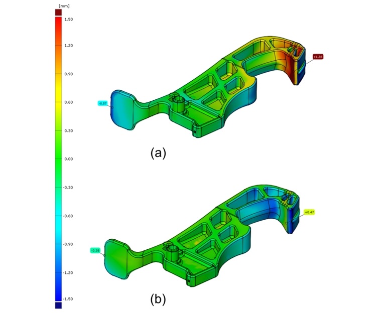
▲ Deformation a) original design b) deformation pre-compensation
In order to reduce the warping deformation of plastic parts, starting from the injection molding process parameters, we can consider the following four aspects:
8.1 Reduce injection pressure and speed
High injection pressure and flow rate will produce high shear rate, forming the internal stress of plastic parts, so that plastic parts warped deformation.
The lower injection pressure can reduce the molecular orientation tendency of plastic and reduce its internal stress.
The warping deformation is reduced, and the injection pressure and velocity are minimized as far as practicable.
8.2 Adjust the holding pressure and the holding time
The retaining pressure is too high, the flow residual stress solidified by feeding is high, and the stress is easy to release, resulting in the warping and deformation of plastic parts.
If the retaining pressure is too low, the reflux will occur near the gate, which will not only form the flow residual shear stress, but also form the large volume shrinkage difference and produce high residual tensile and compressive stress, resulting in the warping deformation of plastic parts.
When the pressure holding time is short, backflow will occur near the gate when the screw is backstepping, and large residual stress will be formed.
Therefore, the retaining pressure should be moderate, and the retaining pressure time should be extended until the gate solidifies, so that the residual stress can be smaller.
8.3 Adjust mold temperature
The mold temperature is low and the residual shear stress is large. If there is not enough time to release the residual stress, it is easy to warpage and deformation. Warping can be reduced by increasing die temperature.
But it doesn't have to be cold. For some shapes, low temperature will lead to the increase of the temperature difference between the mold cavity and the mold core, which is easy to produce deformation. In addition, when the mold temperature is lower than the ambient temperature of plastic parts, it will cause deformation or size change due to shrinkage.
Therefore, for the mold temperature, the most important thing is not the temperature level, but the temperature uniformity (equilibrium) including the mold core cooling, in order to achieve uniform shrinkage.
8.4 Adjust the Cooling time
Because the plastic parts hold their shape longer in the mold cavity, increasing the cooling time will reduce deformation in many cases.
But for some shapes on the contrary, because of the mold (core) hold tight and other reasons, sometimes increase the cooling time will cause poor release deformation, can not be generalized.
Last word
The warping deformation of plastic parts is always a thorny problem.
On the basis of understanding the non-uniform shrinkage, the preparation of structural thinking, that is, from the plastic materials, plastic parts design, mold structure and injection molding process to prevent and solve, then warping deformation is no longer a problem.