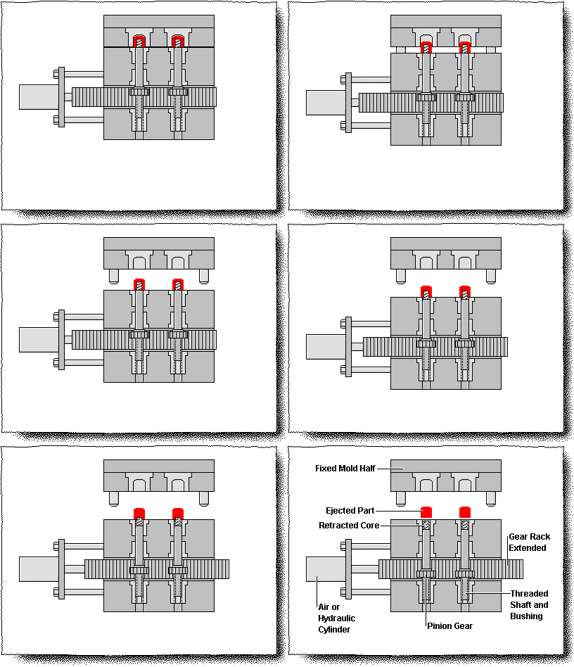
1.1 According to the way of action
1.2 According to the driving method
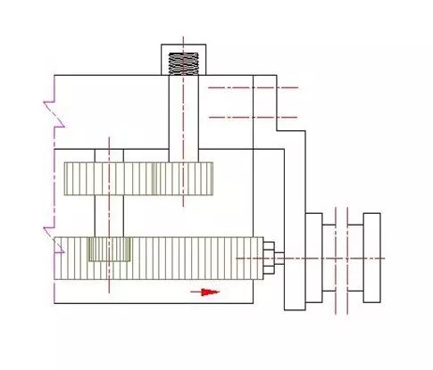
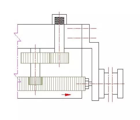
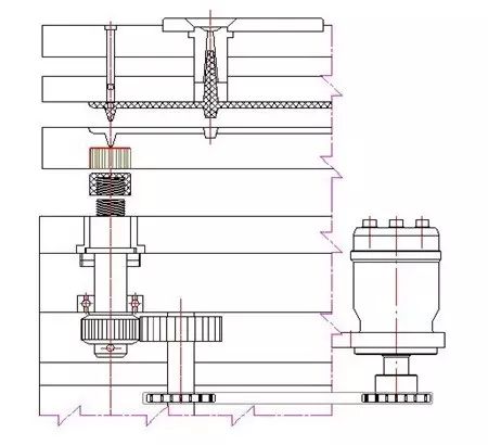
2.1 Must master the following data of the product (see figure below)
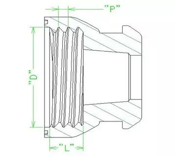
2.2 Determine the number of turns of the threaded core:
U=L/P + Us
Number of turns of U-thread core
Us safety factor, in order to ensure the complete spin out of the thread added margin, generally take 0.25~1
2.3 Determine gear module, number of teeth and transmission ratio:
Modulus determines the tooth thickness of the gear, the number of teeth determines the outer diameter of the gear, and the transmission ratio determines the speed of the meshing gear.
Before this, it is necessary to talk about the parameters and meshing conditions of gears.
The screw unloading mechanism of the die is mostly used in the spur gear, and generally are involute spur gear, so the following is to the involute spur gear as the object of study.
3.1 Basic requirements for gear transmission
3.2 Basic law of meshing of spur gear
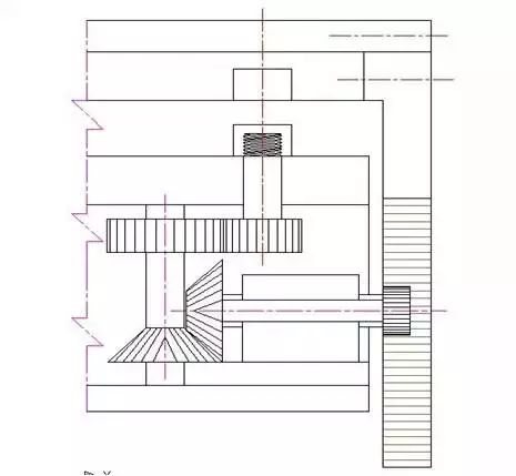
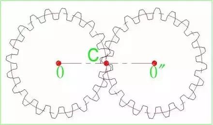
No matter where the two gear profiles contact, the common normal of the two meshing gears made through the contact point must intersect with the center line of the two wheels at a point "C", so as to ensure that the instantaneous transmission ratio of the gear remains unchanged. Connect all "C" points to form two outer tangent circles, which are called indexing circles. The distance between the center of the indexing circle is the distance between the center of the gear circle. See the following figure.
3.3 Parameters of involute spur gear
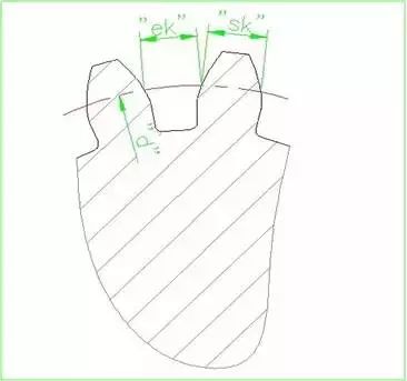
The dividing circle diameter ------ "d" indicates
Dividing circumference -------- "S" indicates
Gear pitch -------- "p" represents
Gear tooth thickness -------- "sk" indicates
Gear groove width -------- "ek" indicates
The number of gear teeth -------- "z" indicates
The gear module -------- is "m"
The gear pressure Angle -------- "alpha" is expressed
Gear ratio -------- "i" indicates
Gear center distance -------- "l" indicates
As far as the demoulding direction is concerned, the internal and external threads are inverted. This kind of product needs rotary screw core (internal thread) or rotary cavity (external thread) demoulding.
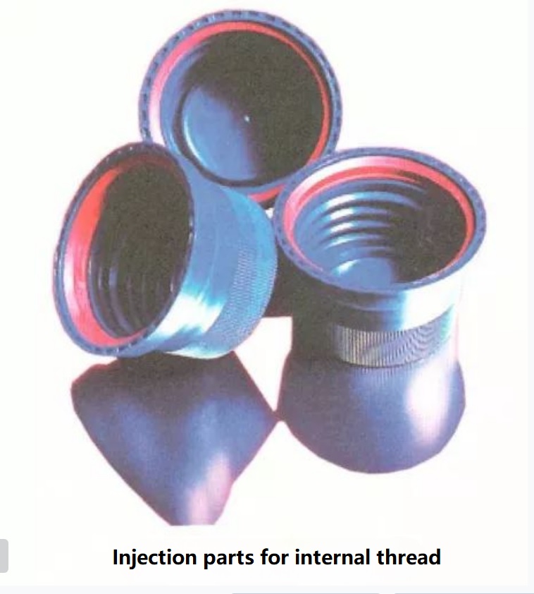
Internal thread
The inner thread is formed on a core with a threaded profile. The core will be wrapped by the product during injection, while the outer surface of the injection part is smooth.
If the internal thread cannot be removed plastically, the release can be achieved by loosening the threaded core or by relying on the telescopic core.
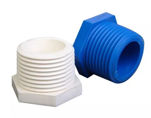
External thread
The external thread is usually finished with a block. The parting surface may not be visible, while the entire core is rotating. Whether it is necessary to rotate the core or the cavity, it is necessary to install gears on the moving or fixed die side. Gears can be driven by a servomotor, rack, or a screw driven shaft.
Either with external or internal threads, the molded parts are held in place by grooves around them or by special stops. In the latter case, the trace of the stop bump can be seen inside the product. If you do not want to see such marks on the final product, you need to complete the rotary core-pulling while the mold is closed.
Threading mechanism
In order to make the threaded core release smoothly, the injection parts need to stop. Depending on the shape of the product, there are many ways to remove thread.
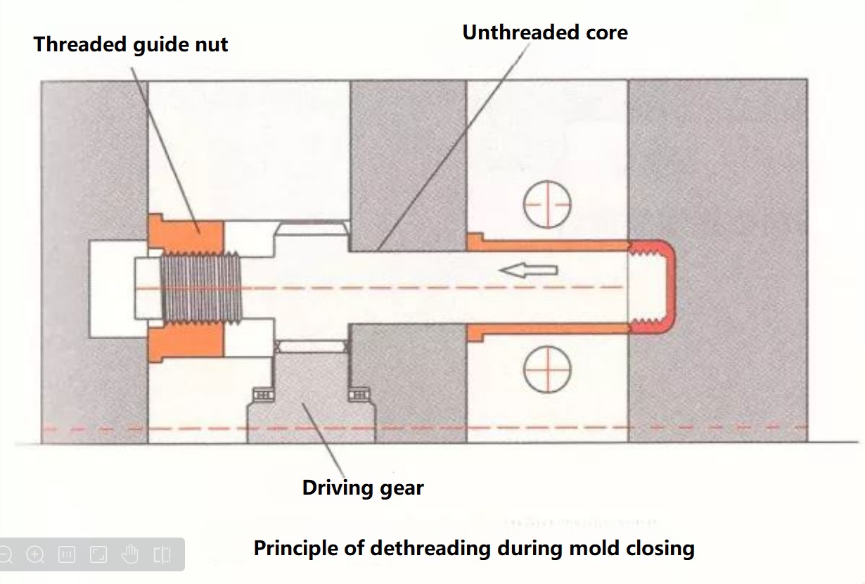
1) Thread off in closing condition
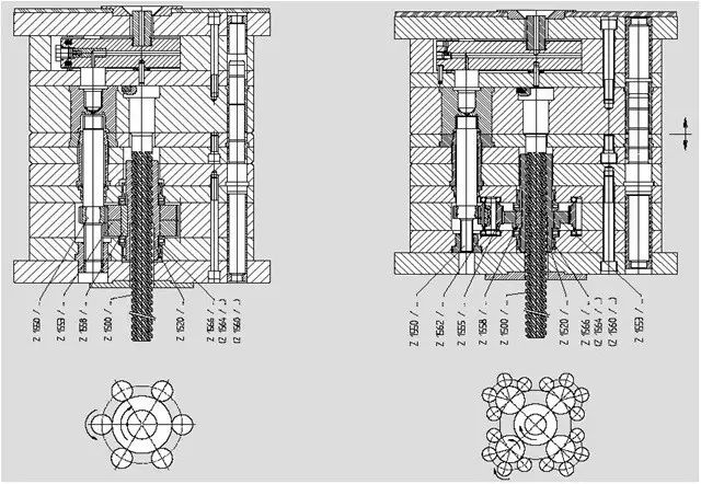
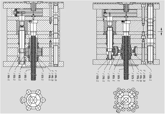
The threaded core is controlled by the pilot thread and retracted. Note that the dip Angle of the lead thread should be the same as that of the spin thread. Stop the rotation needs to rely on the product die side of the geometric structure itself. After the thread is removed, the ejecting mechanism of the equipment moves forward, and the product is ejecting from the discharge plate. The threading principle of mold closing is shown in the figure below.
Advantage: The last thread of injection parts will not be damaged.
Disadvantages: The threaded core needs to be rotated back from the injection position, which will prolong the molding cycle.
2) The discharge plate is off thread
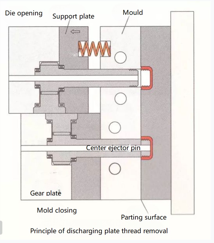
The discharge plate is installed on one side of the fixed die, and the rotating core does not retreat. When the machine is opened and equal to the pitch, the discharge plate is pressed on the fixed form by the spring force. Then ejection system forward, the product from the discharge plate ejection. See Figure 2.12 for the principle of unloading plate threading.
Advantages: There is no need to design expensive threaded core and lead screw, and no loss of time to turn threaded core.
Disadvantages: The locking force will be lost due to the resistance of the spring.
3) Unthread in ascending motion
At this time, the injection molding part is attached to the discharge plate, and a special stop block is needed to stop the rotation. In this case, the threaded core needs to retreat. Instead of pressing the spring, the rotating core is guided back by the guide thread to release the product.
Advantages: The thread quality of the product is very good.
Disadvantages: The manufacture of threaded core and lead screw is expensive.
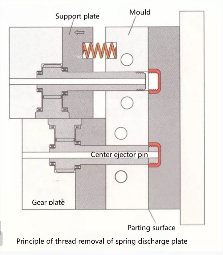
4) Spring driven push plate unthreaded
The core does not retreat, but is pressed by a spring on the supporting plate. At this time on the injection molded parts to just molding thread screw, which carry a large load. So when the threaded product leaves the core, the last thread is in danger of being damaged. See Figure 2.13 for the principle of screw stripping of spring discharge plate.
Advantages: Low manufacturing cost.
Disadvantages: poor thread quality.
For dethreaded die, injection parts rely on rotating core (internal thread) or rotating cavity, also known as cavity (external thread) release.
