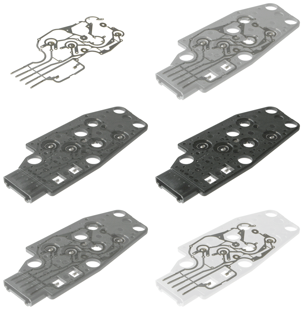
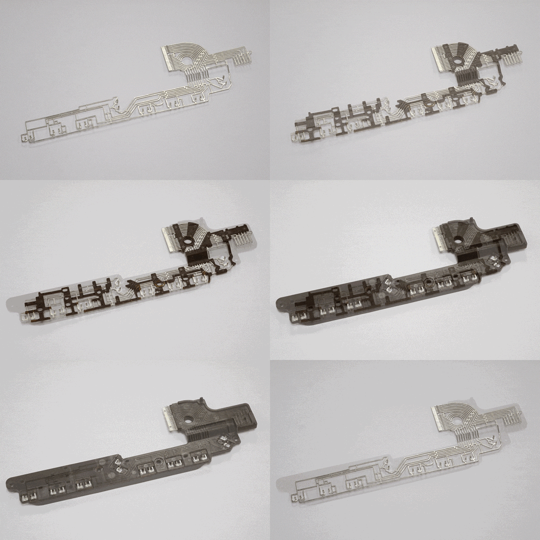
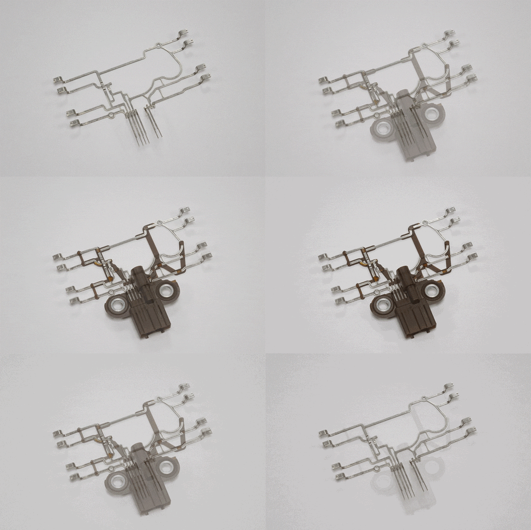
1>Artificial placement: this will greatly increase the injection molding cycle, suitable for small batch production or complex structure of the product;
2>Automatic placement: This is a better choice for mass production, which helps reduce manual errors, improve efficiency, shorten injection molding cycles and improve product reliability.
>Advantages of insert injection molding
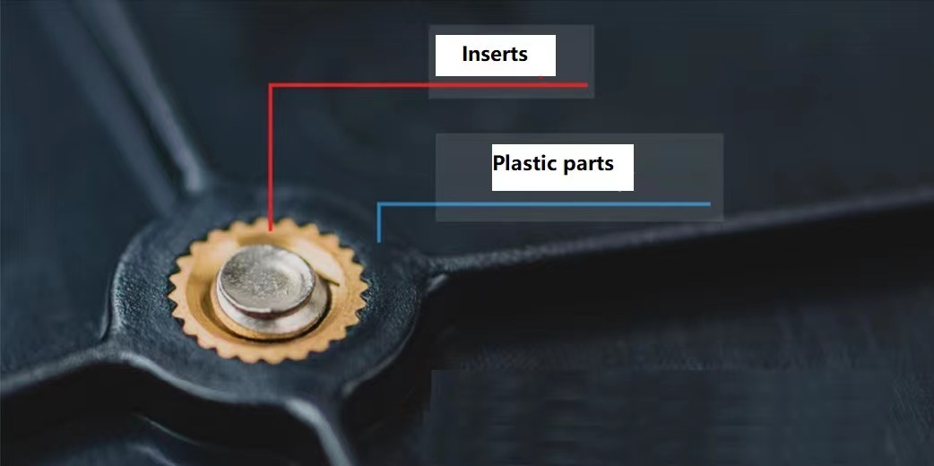
Plastic is easy to form, elasticity and metal rigidity, strength and heat resistance of the mutual combination of complement can be solidly made into complex metal plastic integrated products; Reduce the size and weight of the product;
Using the combination of plastic insulation and metal conductivity, the molding products can meet the basic function of electrical products; It can also meet some special requirements, such as magnetic permeability, wear resistance and fastening, etc.
Adding metal inserts into plastic can improve the strength of plastic parts;
Injection molding of inserts increases the flexibility of product design and provides new possibilities for the combination of plastics with metals and other parts.
Avoid secondary processes such as hot melting, welding and riveting, and have the opportunity to reduce assembly time and cost;
Inserts are not only limited to metal, but also cloth, paper, wire, plastic, glass, wood, coil, electrical parts and plastic parts, etc.
For the rigid forming products and the flexor elastic forming products on the rubber sealing gasket, the complex operation of arranging the sealing coil can be saved after the product is made by injection molding on the matrix, which makes the automatic combination of the last process easier.
Because it is a combination of molten plastic and metal inserts, and pressed into the forming method compared, metal inserts can be designed more narrow gap, higher product reliability; Easier to pass tests such as vibration;
Appropriate plastics and forming conditions, that is, products prone to breakage (such as glass, coils, electrical parts, etc.), can be sealed and fixed by plastics.
Select the appropriate mold construction, the insert can also be completely sealed into the plastic.
The combination of vertical injection molding machine and manipulator, insert product line device, etc., insert molding engineering can realize automatic production.
>Defects of insert injection molding
The placement of inserts often complicate the mold structure, prolong the injection molding cycle, increase the manufacturing cost, and increase the difficulty of automatic production;
The coefficient of thermal expansion between the insert and plastic is inconsistent, which is easy to make the final product produce internal stress, and cause the product rupture; This point is particularly obvious in the injection molding of nut inserts;
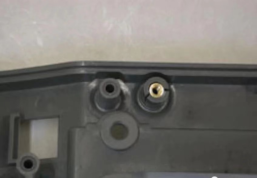
Or because the coefficient of thermal expansion of the insert and plastic is inconsistent, resulting in deformation of the product;

Inserts (especially nut inserts) often need to be preheated or dried to reduce the internal stress;
The insert must be well fixed in the mold, otherwise it is easy to shift or deformation under the impact of the solution;
Once the injection molding of the insert produces bad products, such as bad injection molding, insert omission, poor position, will cause the whole product scrap, the cost is huge:
Injection molding of insert is not conducive to product recycling and scrapping.
>Application of insert injection molding
Insert injection molding is widely used in automotive, medical, electronic products and connectors.
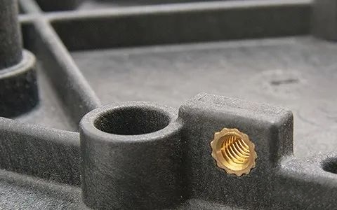
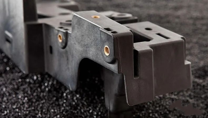
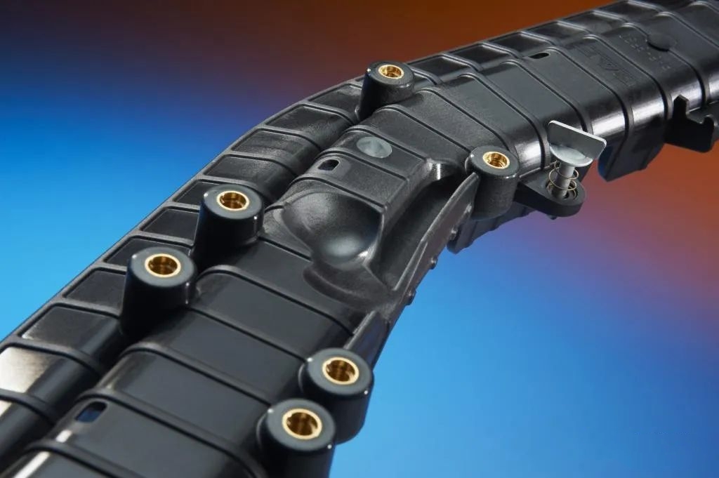
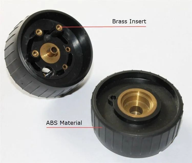
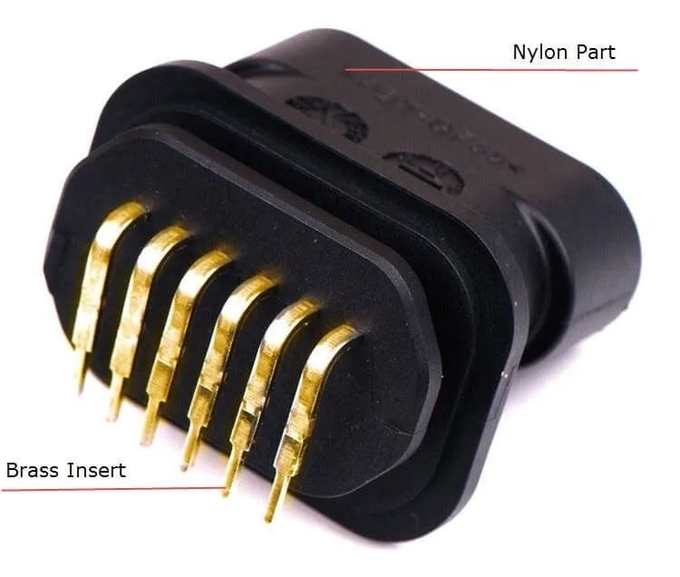
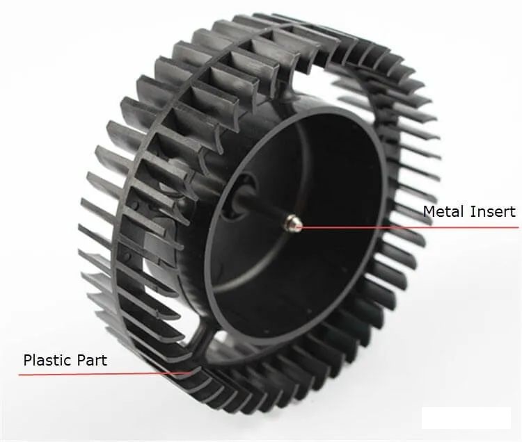
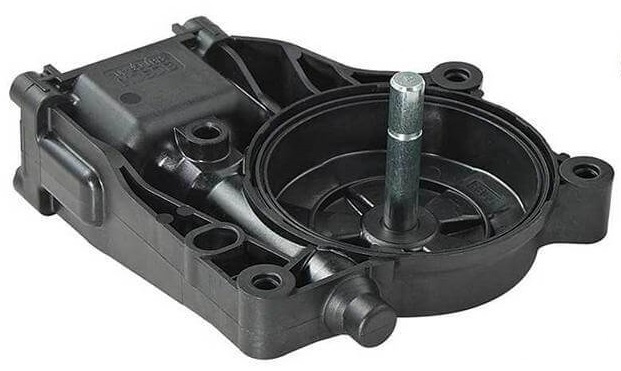
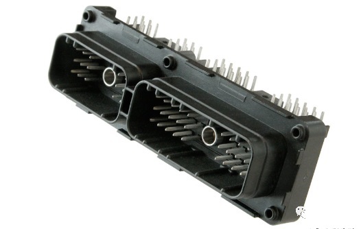

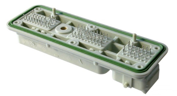
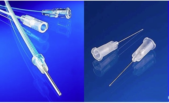
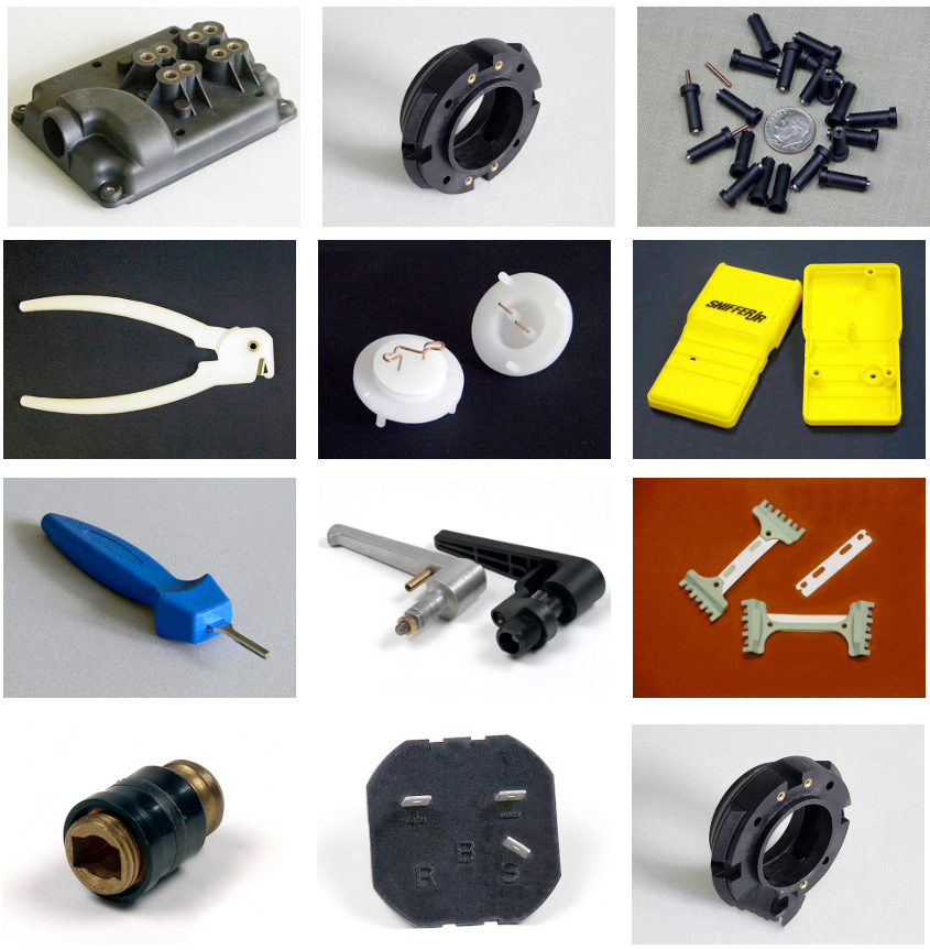
In the design of injection molding, we must fully consider the process characteristics of injection molding, DFM design;
Design guidelines for injection molding of inserts include:
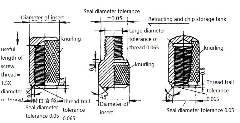
▲ Insert itself DFM design
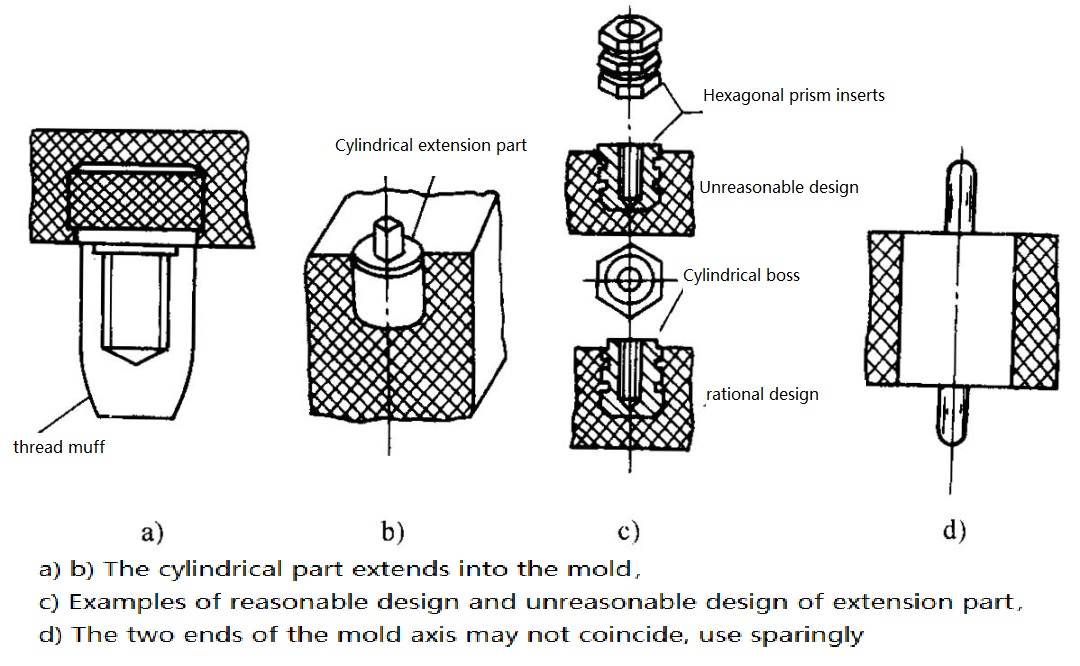
▲ Design of the extension part of the insert
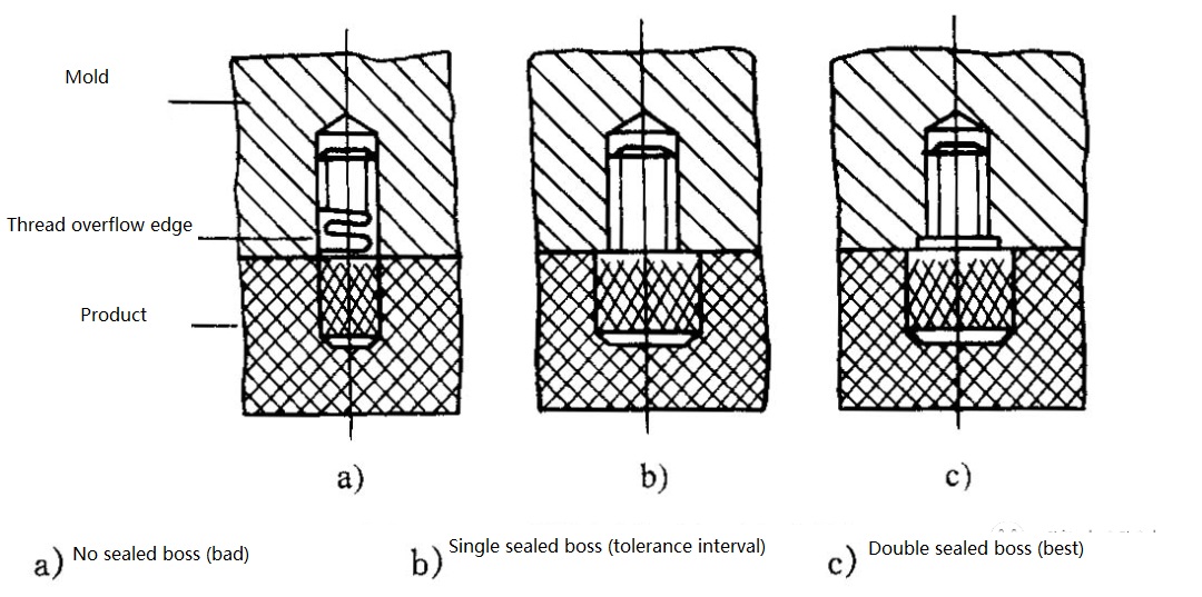
▲ Design of insert boss
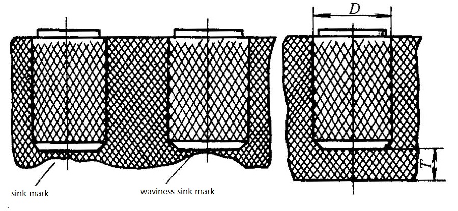
▲ The distance between the insert and the bottom
When the distance is too small, the design shown below can be used;
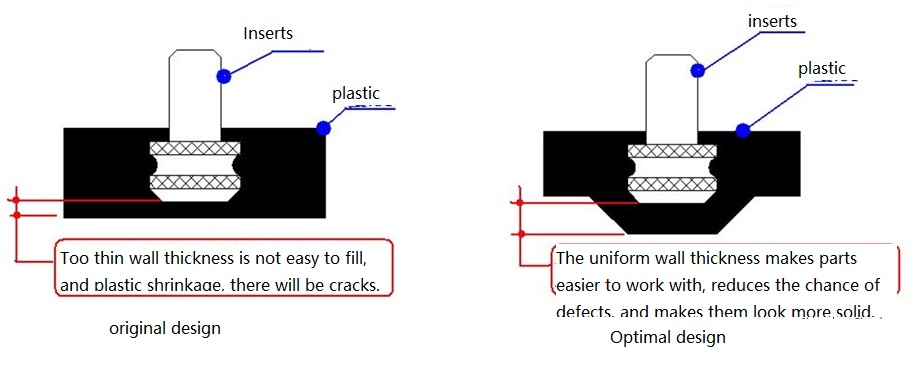
▲ Ensure even wall thickness
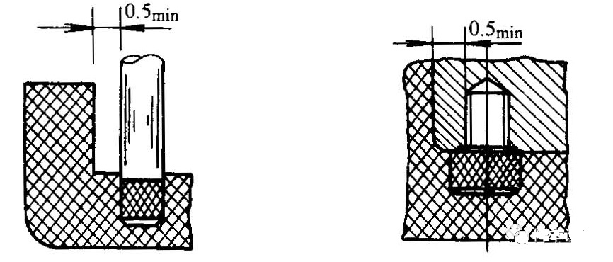
▲ The distance between the insert and the side wall
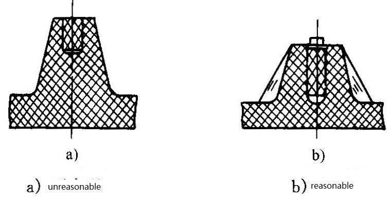
▲ Insert in boss
Small cylindrical inserts can be used in the middle slot or surface rhomboid knurled structure planted in the plastic matrix, knurled groove depth of 1~2mm;
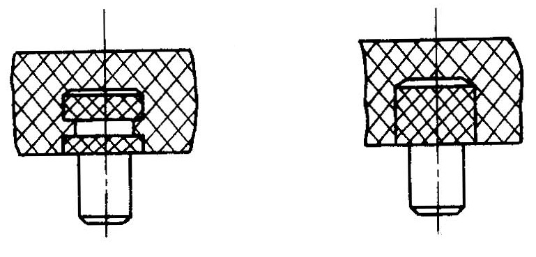
▲ Fixing of small cylindrical inserts
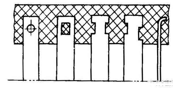
▲ The fixing of plate and sheet inserts

▲ Fixing of rod inserts (head deformation)
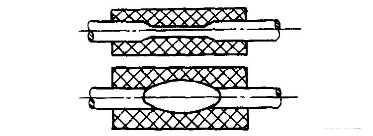
▲ Fixing of tubular inserts (middle deformation)
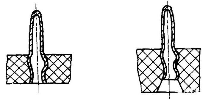
▲ The fixation of tubular stamping parts (middle deformation)
>Punch holes in plastic terminals
>Shaped terminal in plastic;
>Plastic terminal bending;
>Plastic terminals increase roughness, convex and convex points;
>Increase the thickness of plastic walls.
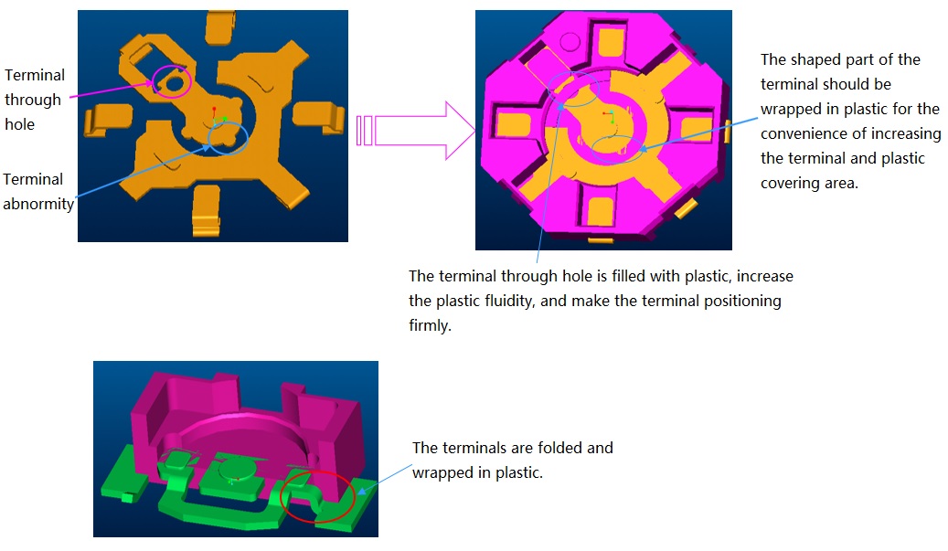
▲ Terminal insert hole, shaped, bending
Nut inserts are one of the most common inserts. The nut inserts and corresponding plastic parts of the pillar must be correctly designed, otherwise there will be insufficient pulling power, pillar fracture and other quality problems.
Three embedding methods of nuts:
>Hot melt nut
Hot melt embedding is the most common, the most common embedding way, generally with hot melt machine and manual electric soldering iron buried nails;
>Insert injection molded nut
Injection molding is generally embedded on the nut pillar aperture requirements are very strict, aperture control within 0.05mm, because the product is fixed by ModingPin placed in injection molding mold, nut aperture to injection molding machine PIN pin size to control;
>Ultrasonic nut
Ultrasonic embedding is a kind of ultrasonic vibration, so that the friction between the nut and the workpiece surface and the internal molecules and the temperature of the transmission to the interface increases, when the temperature reaches the softening temperature of the workpiece itself, the nut is embedded in the rubber parts, when the vibration stops, the workpiece at the same time under a certain pressure cooling setting.
Each of the three methods has advantages and disadvantages. This article discusses the insert injection nut.
The outline structure of the insert nut
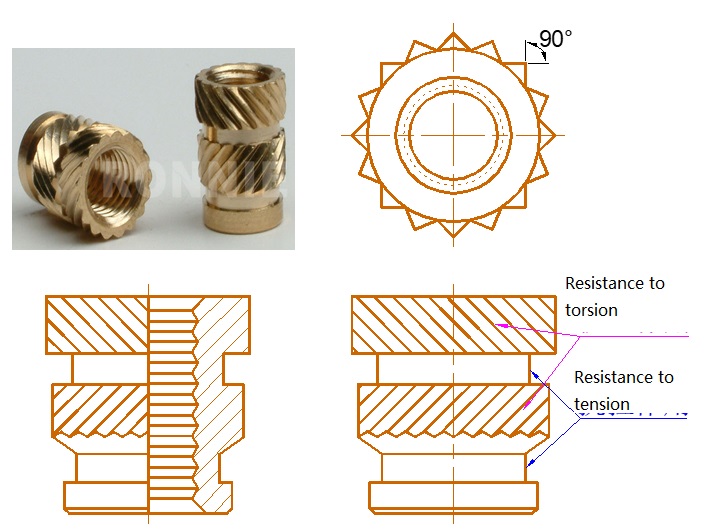
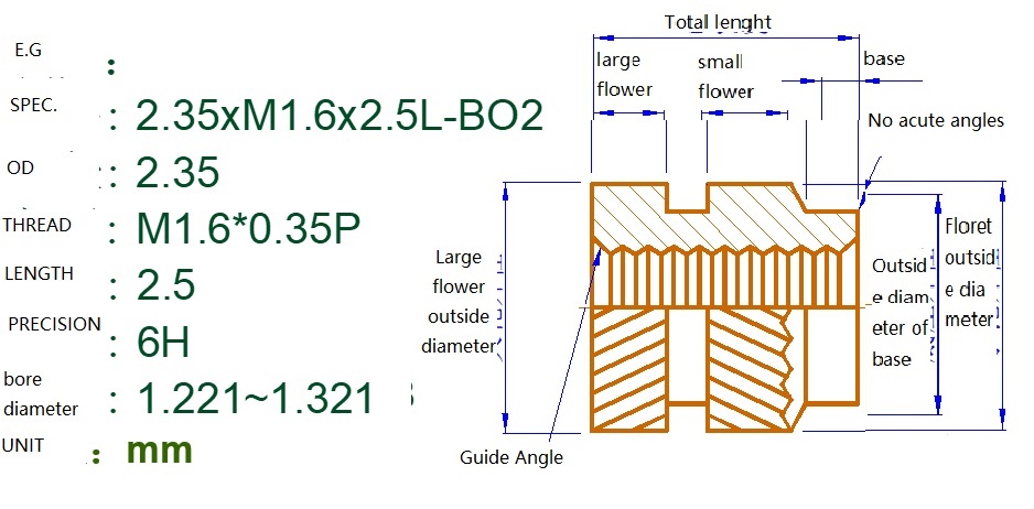
Example specifications for insert nuts
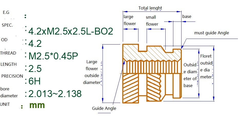
Plastic pillar design and nut selection
Basic dimensions of nuts and plastic strut
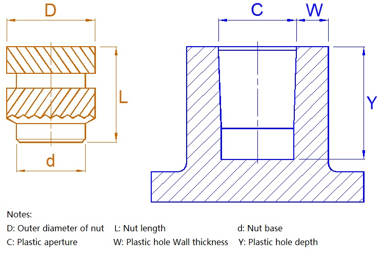

d size is the nut base, also known as the guiding positioning part, before embedding with the plastic part C, so the bottom of the nut part d is smaller than the plastic part of the pillar diameter C size, to facilitate positioning;
D size is the outer diameter of the nut, which matches the inner diameter of the plastic pillar C size. Generally, the inner diameter of the plastic phone nut is about 0.25-0.3mm smaller than the outer diameter of the nut.
L size is the length of the nut, which is matched with the hole depth of the plastic pillar Y size. Generally, the depth of the plastic hole is 0.5-1.0mm larger than the nut height (length) for storage;
W is the thickness of the plastic hole wall. Generally, the hole meat thickness of the plastic pillar is above 0.8-1.0mm. The bigger the nut size, the bigger the meat thickness. (See parameters in the table below)
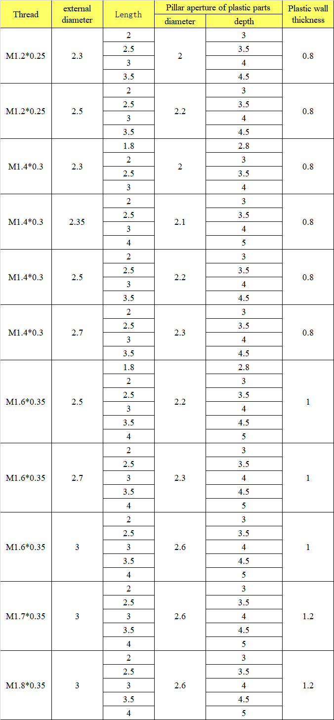
> The correct size of the plastic strut hole is very important. Plastic parts pillar hole is too large, the nut buried in the plastic can not get glue, will produce insufficient torsion tension phenomenon; Plastic parts pillar hole is too small, will produce rubber overflow or rupture phenomenon;

> If there is no problem with nut size and plastic size, and abnormal phenomena occur, it will usually be considered through some optimization design to improve;

Due to the plastic parts pillar depth is shallow, such as the choice of double twill nuts, in the nut size ratio deployment, especially on the embowel, embowel section difference is short, such nuts buried in the plastic, embowel eat plastic surface too little plastic, will produce insufficient torsion tension phenomenon, so it is generally recommended that the plastic parts pillar hole depth is set at more than 2.5mm, It is recommended that the nut length be longer than 2.0mm.
Improvement plan: In this case, if it is not convenient to change the mold, it is suggested to change the nut shape to monodiagonal BS1, as shown in the figure on the right. In this way, the difference of embossment section will be increased, and the plastic of embossment eating rubber surface will be increased, thus increasing the torsion tension.
>Plastic parts pillar hole overflow or crack

Due to the choice of the style nut in the left picture, after embedding plastic, A1, A2 expansion, B is sharply contracted, resulting in plastic extrusion difficulties, the upper and lower end of the nut is prone to overflow phenomenon, seriously affecting the appearance of the product;
Improvement plan: With the "C" part as the guide positioning, so that the nut can be safely put into the plastic hole, improve the efficiency and yield, due to the C end of the guide part, A2 out of a certain amount of glue, also reserved enough glue to A1 part, at the same time because A1, A2 part is 90° intersection Angle 45° twill, and can form a high strength node, The torque force on the circumference of the impedance greatly increases the torque tension.