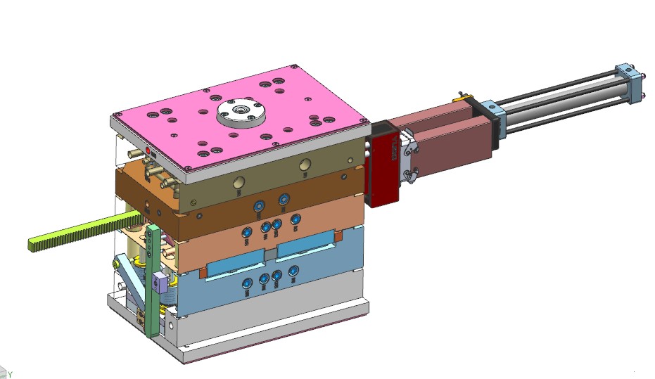
This paper introduces a fully automatic rotary screw thread core pulling mould structure, rotation driven by oil cylinder, products for the automotive parts, internal thread.
Mold specifications :300*450*580mm
Product basic information
|
Product name |
Worm-and-nut |
Cavities material |
ASPPM S136(HRC48-52) |
|
Product material |
PA66+GF50 |
Die set brand |
Futaba |
|
Mold Cavity |
1*4 |
Hot tip brand |
YUDO |
| Shrinkage rate |
1.005 |
Glue way |
The hot nozzle turns and dives into the glue |
| Product surface requirements |
microgroove |
Mold type |
Two-plate mold |

Mold feeding method
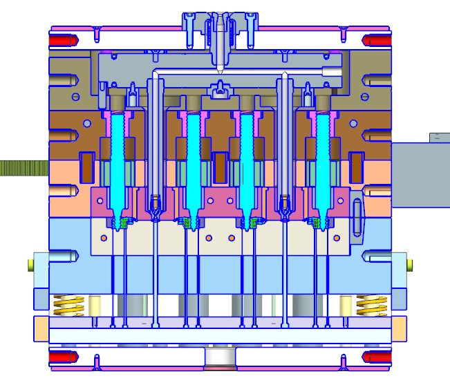
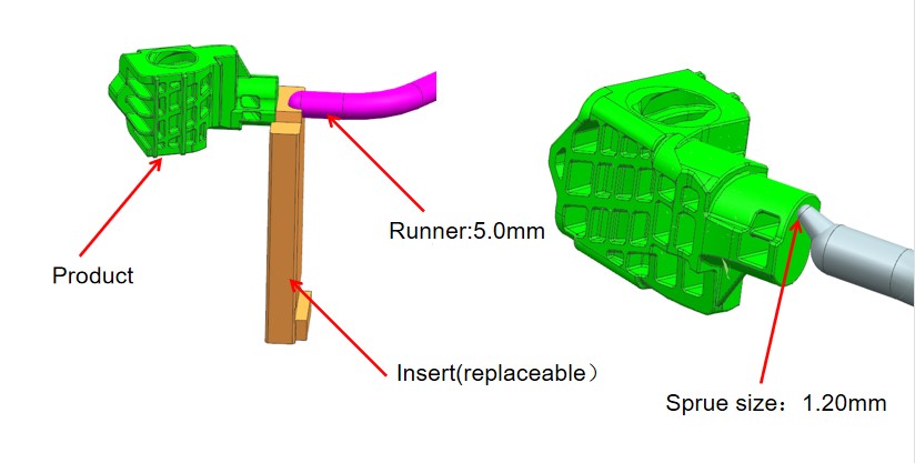
The mold adopts the front die to rotate the thread to pull the core. The thickness of the front die part is up to 140mm, in order to reduce the length of the main channel and avoid raw materials waste, so the use of two open hot runner system, a hot nozzle is responsible for two hole products, diving into the glue, hot runner brand YUDO, as shown below:
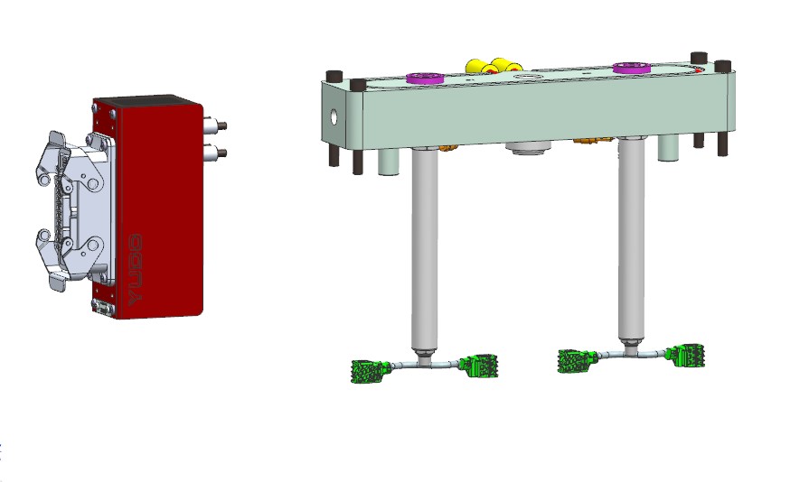
Parts of raw materials for PA66 + GF50, brazing content reached 50%, mold diving into glue point is easy to damage, so in the mold insert into glue point design, easy to change after servicing.
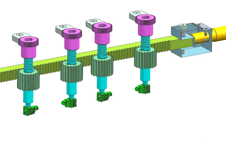
Thread core pulling rotation structure
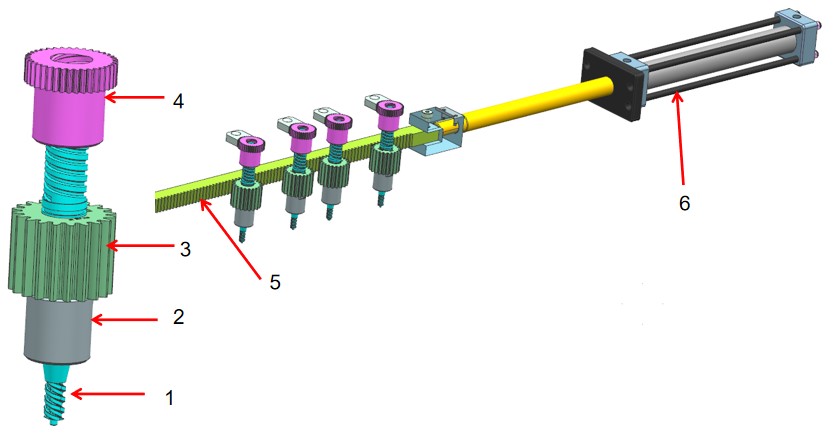
The thread core pulling rotation structure includes:
1. Screw rod; 2. Guide sleeve; 3. Gear; 4. Threaded braces; 5. Rack; 6. Oil cylinder
Structure principle of thread core pulling
1. The number of thread turns of the parts is only 2 turns, and the core-pulling stroke is very short, so the rack directly drives the gear.
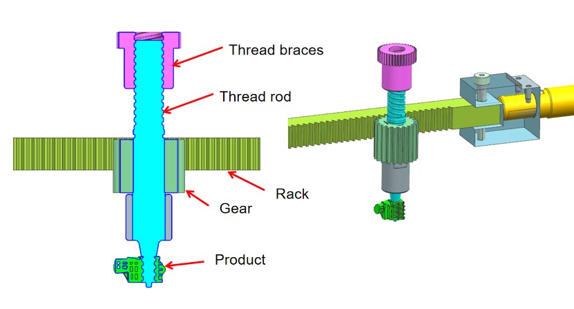
2. The cylinder moves the rack, the rack synchronously drives the gear to rotate, and the thread rod completes the tooth withdrawal along the thread sleeve track.
Oil cylinder core pulling stroke calculation:
1. Screw rod rotating ring C = product thread ring +0.5 turns =2.5 turns
2. Diameter of gear indexing circle D= modulus M* tooth number Z=40mm
3. Oil Cylinder core pulling stroke S= dividing circle diameter D*π* rotating circle C
That is (40x3.14x2.5)=314mm
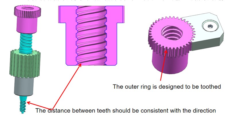
Design of threaded braces:
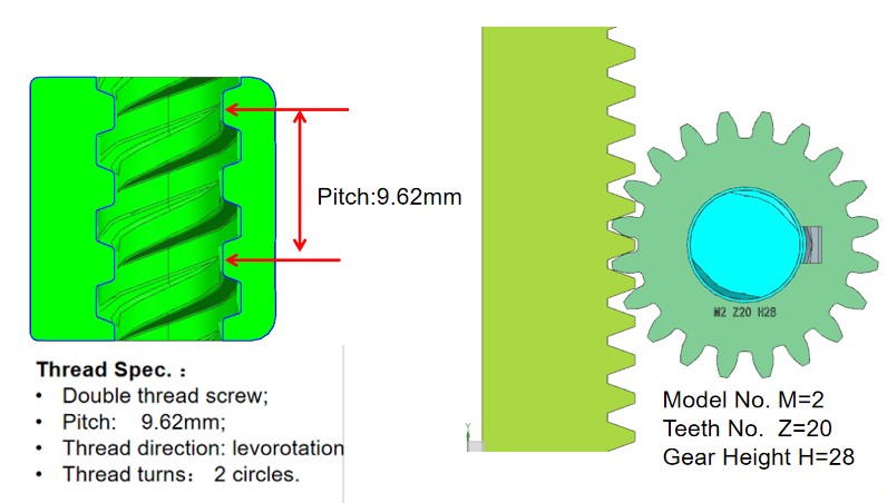
1. The pitch and direction of the thread braces must be consistent with the thread rod to ensure synchronous movement.
2. Threaded braces are made of bronze with hardness up to HRC32-38.
3. The outer ring of the thread retainer hanger is designed to be toothed, which is used for positioning of the teeth and adjusting the height and direction of the thread retainer.
4. The number of teeth on the outer ring of the braces is determined according to the thread distance of the product, the larger the distance between teeth, the more teeth are designed.
Ejection design
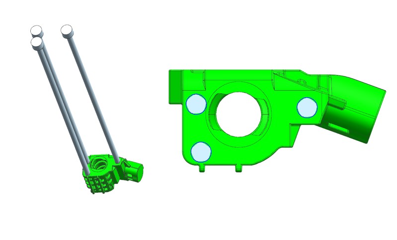
Design three round thimbles for ejection as shown below
Thread core pulling in the front die, die opening action is as follows

